Underground Mining Machine

a mining machine and underground technology, applied in the direction of mining structures, percussion drilling, take-up reels/drums, etc., can solve the problems of not being able to recognize the need to operate the underground mining machine in any different manner, damage and the need to repair or replace power cables,

Active Publication Date: 2017-07-06
CATERPILLAR GLOBAL MINING EQUIP LLC
View PDF3 Cites 0 Cited by
  • Summary
  • Abstract
  • Description
  • Claims
  • Application Information

AI Technical Summary

Benefits of technology

[0006]In accordance with one aspect of the present disclosure, a system for managing an underground mining machine is disclosed. The system may include a reel-in switch located in an operator station configured to generate a plurality of reel-in signals and a reel-out switch located in the operator station configured to generate a reel-out signal. The system may additionally include an electronic controller in electrical communication with the reel-in switch and the reel-out switch. The electronic controller may be configured to receive the plurality of reel-in signals from the reel-in switch and enter into two or more reeling-in modes in response to the plurality of reel-in signals.

Problems solved by technology

In this instance, the operator may accidentally overrun the power cable, leading to damage and the need to repair or replace the power cable.
Additionally, while moving the underground mining machine in a forward direction, and when an amount of the power cable still coiled around the cable reel is nearing its end, the velocity at which the operator is moving the underground mining machine may leave little time for the operator to stop the underground mining machine before breaking the connection between the power cable and the underground mining machine.
While arguably effective for its specific purposes, such prior art system only attempts to match cable reel speed with underground mining machine speed, failing to recognize a need to operate the underground mining machine in any different manner.
Such system also relies on a fluid-based control system, and thus there may be lag between the underground mining machine speed and the cable reel speed, leading to sagging and stretching of the power cable.
Also, as a result of such lag, the momentum of the machine may still be great enough that the machine continues to move even after receiving a machine stop signal.
In this instance, the power cable may break away from the underground mining machine.

Method used


Image

  • Underground Mining Machine
  • Underground Mining Machine
  • Underground Mining Machine

Examples


Embodiment Construction

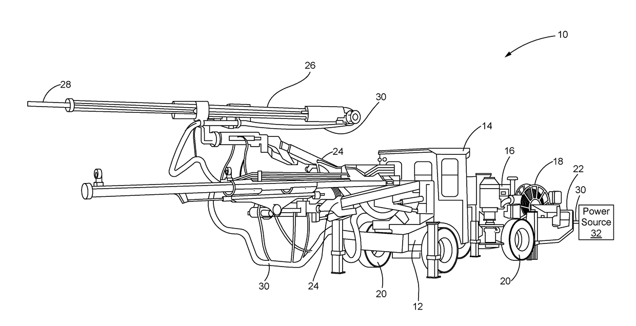
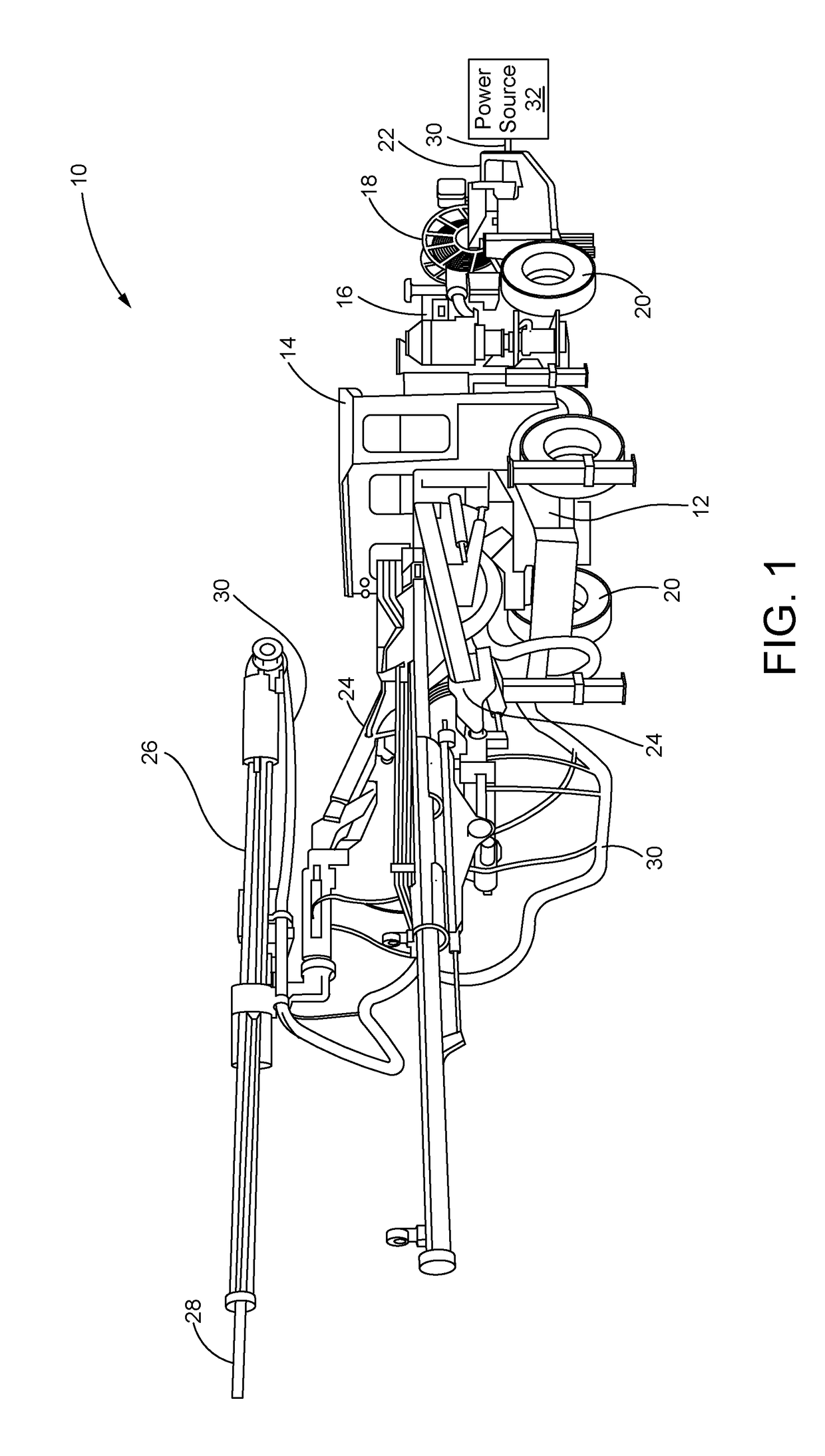
[0014]Various aspects of the disclosure will now be described with reference to the drawings, wherein like reference numbers refer to like elements, unless specified otherwise. Referring to FIG. 1, a perspective view of an underground mining machine 10 is illustrated, according to an aspect of the disclosure. As seen there, the underground mining machine 10 may include a chassis 12 supporting an operator station 14, a motor 16 or other power supplying engine and a cable reel 18. The chassis 12 may be supported by wheels 20 or other ground engaging members such as endless tracks and the like. Further, the underground mining machine 10 may include a motor control cabinet 22 wherein some functions of the underground mining machine 10 may be controlled separately from the operator station 14 as described in fuller detail below. While the underground mining machine 10 depicted in FIG. 1 is a jumbo drill, the teachings of the present disclosure are not limited to jumbo drills. Rather, the...


PUM


Abstract

A system for managing an underground mining machine is disclosed. The system may include a reel-in switch located in an operator station configured to generate plurality of reel-in signals, and a reel-out switch located in the operator station configured to generate a reel-out signal. The system may additionally include an electronic controller in electrical communication with the reel-in switch and the reel-out switch. The electronic controller may be configured to receive the plurality of reel-in signals from the reel-in switch and enter into two or more reeling-in modes in response to the plurality of reel-in signals.

Description

TECHNICAL FIELD[0001]This disclosure generally relates to an underground mining machine and, more particularly, to systems and methods to manage an underground mining machine.BACKGROUND[0002]Underground mining machines are commonly used around the world to extract minerals, metals and other materials from various hard and soft rock environments. One example of an underground mining machine is a jumbo drill, although many other types exist. The underground mining machine may include a reeling system that may include a power cable coupling a power source for the machine to a working implement of the machine. A cable reel may also be rotatably associated with the underground mining machine and be configured to coil and uncoil the power cable. Further, the reeling system may include a cable reel-motor rotationally engaged with the cable reel. The cable reel-motor may be configured to rotate the cable reel in a first direction when coiling the power cable and rotate the cable reel in a s...

Claims


Application Information

Patent Timeline
Patent Type & Authority Applications(United States)
IPC IPC(8): B65H75/42B65H75/44H02G11/02E21B1/00
CPCB65H75/425H02G11/02B65H75/4484E21C3/00B65H2701/34E21F17/06
Inventor SZALKO, JAMES R.GLOVER, REX A.
Owner CATERPILLAR GLOBAL MINING EQUIP LLC
Why Eureka
Try Eureka