Floating Swimming Pool Cover

Active Publication Date: 2017-07-13
STONE JR DAVID B
View PDF5 Cites 6 Cited by
  • Summary
  • Abstract
  • Description
  • Claims
  • Application Information

AI Technical Summary

Benefits of technology

The present invention is a floating swimming pool cover that reduces evaporation and retains heat. It is made of corrugated polyethylene with corrugations on the surface that contact the water, creating a vapor barrier. The cover can be wound onto a storage shaft when not in use and is pulled off the pool to cover it. An external drive motor can be used to control the operation of both the drive shaft and the storage shaft. The invention includes an outer housing with both the storage shaft and the drive shaft, a hinged ramp to support the movement of the cover, and a pressure shaft to keep the cover in contact with the drive shaft. The invention also includes a vapor barrier sheet with corrugations that engage with gear teeth on the drive shaft to impart forward movement of the sheet.

Problems solved by technology

Swimming pools lose a significant amount of heat and water through surface evaporation.
This can not only add considerable expense, but may also shorten the season during which the pool is usable.
Similar vapor barriers are also beneficial for use with indoor pools, where evaporated water not only requires adding heat to the pool, but also produces humidity issues in the pool room.
While useful for relatively small pools, the effort required to cover larger, competition-sized pools is problematic.
That is, the covers are challenging to put on and take off as they often do not hold their shape or wind up “true”.
And even if it is possible to evenly roll up a cover of such an extensive size, it is difficult to find a place to store the cover where it isn't an eyesore (and where it is protected when not in use).
Since they need to be individually placed and removed, their use is time-consuming.
Again, these pads present storage problems.
While effective, this type of configuration is obviously expensive and cannot be used on large pools.

Method used


Image

  • Floating Swimming Pool Cover
  • Floating Swimming Pool Cover
  • Floating Swimming Pool Cover

Examples


Embodiment Construction

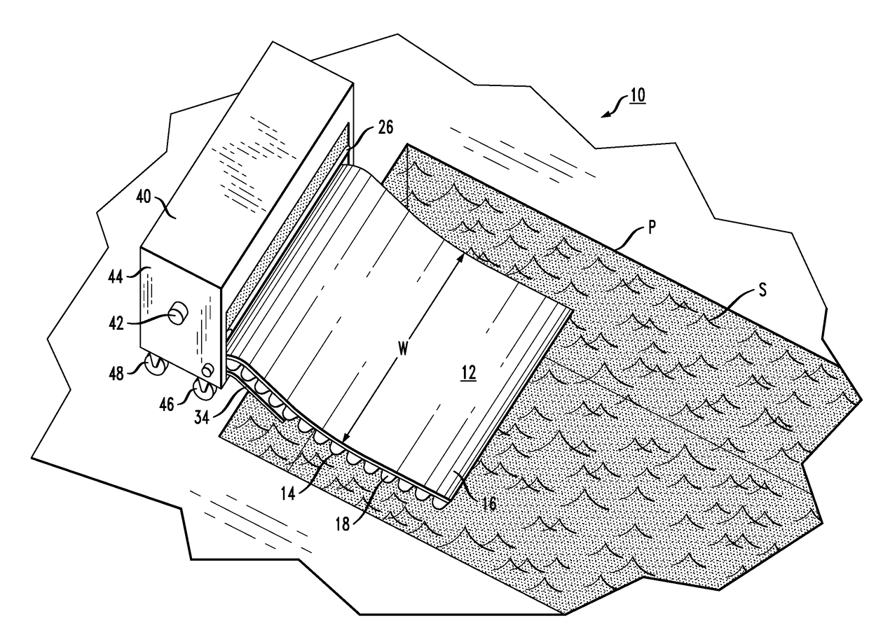
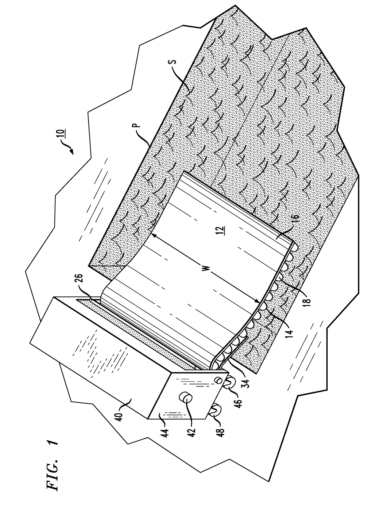
[0022]FIG. 1 illustrates an exemplary floating pool cover apparatus 10 formed in accordance with the present invention. In the view of FIG. 1, the cover is partially deployed (that is, in the process of being played out) onto a pool P. More particularly, the cover is being deployed so as to float on water surface S within pool P. Apparatus 10 is shown as being positioned at an edge of pool P. It is contemplated that a particularly advantageous embodiment of the present invention is to utilize an apparatus 10 that is sized to cover an individual lane of a pool (for example, an indoor pool of a specific length for competitive swimming). When used in this context, a multiple number of the same apparatus may be lined up along the edge of the pool, with each cover apparatus 10 used to cover an individual lane.

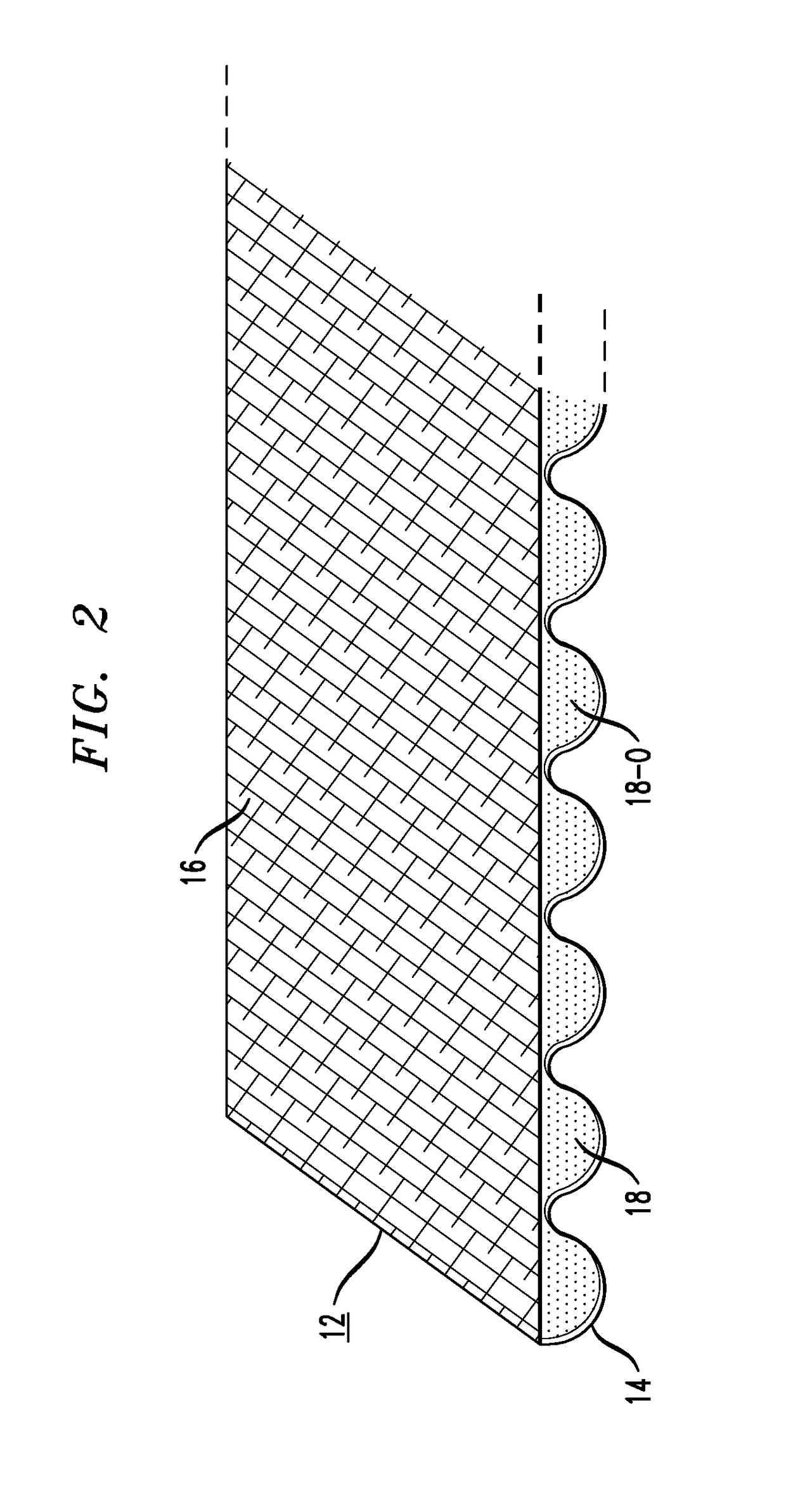
[0023]As will be discussed in detail below, cover apparatus 10 includes a vapor barrier sheet 12 that is formed of a flexible material (preferably, polyethylene) having a corrugated...


PUM


Abstract

A pool cover apparatus includes a sheet of corrugated polyethylene as a vapor barrier, where the sheet is wound onto a storage shaft when not in use. A drive shaft is disposed in a spaced-apart relationship with the storage shaft. When it is desired to deploy the sheet to cover the surface of a pool, the sheet passes over the drive shaft and the corrugations on the polyethylene sheet engage with the teeth on the drive shaft. Thus, as the drive shaft rotates, it causes the vapor barrier sheet to continue to move out and away from the shafts and cover the pool. Conversely, when it is desired to remove the sheet from the pool, the storage shaft is engaged, rotating in a manner that functions as a take-up reel and winds the vapor barrier sheet up on the shaft for storage.

Description

CROSS-REFERENCE TO RELATED APPLICATIONS[0001]This application claims the benefit of U.S. Provisional Application Ser. No. 62 / 275,851, filed Jan. 9, 2016 and herein incorporated by reference.TECHNICAL FIELD[0002]The present invention relates to a floating swimming pool cover useful in reducing evaporation and retaining heat and, more particularly, to a floating cover formed of corrugated polyethylene, with the corrugations formed along the surface that contacts the water, creating a vapor barrier.BACKGROUND OF THE INVENTION[0003]Swimming pools lose a significant amount of heat and water through surface evaporation. To maintain a comfortable temperature in the pool, as well as to keep a relatively consistent water level, it is necessary to frequently add both water and heat to the pool. This can not only add considerable expense, but may also shorten the season during which the pool is usable. It is known to use a removable cover that functions as a vapor barrier to reduce evaporation...

Claims


Application Information

Patent Timeline
IPC IPC(8): E04H4/10
CPCE04H4/101
Inventor STONE, JR., DAVID B.
Owner STONE JR DAVID B
Why Eureka
Try Eureka