Push switch

Active Publication Date: 2017-07-27
TOKYO PARTS IND CO LTD
View PDF3 Cites 7 Cited by
  • Summary
  • Abstract
  • Description
  • Claims
  • Application Information

AI Technical Summary

Benefits of technology

The push switch in this invention allows for easy replacement of the cap with different color options, while still maintaining the seal and durability of the button. This improves the reliability of the push switch.

Problems solved by technology

However, with the vehicle switch described in Japanese Patent Laid-Open Publication No. 2006-100013, because the base and the decorative member are connected by fitting a projection provided on the decorative member in a hole provided in the base, which is made from the rubber material, the seal characteristics are readily degraded and there is a risk of water penetrating into the space in which the switch main body is disposed.
Furthermore, with the vehicle switch described in Japanese Patent Laid-Open Publication No. 2006-100013, if a large pushing force acts on the button, the thin flexible portion provided in the base, which is made from the rubber material, is unduly stretched, such that there is a risk of the base itself being damaged.
However, because the structure is such that when the pushbutton part is push-operated, a portion of the soft pushbutton part is trapped between the pushbutton part that is made from the hard material and the switch case that is made from the hard material, there is a risk that the portion that is trapped between the pushbutton part and the switch case will be damaged by repeated push-operations and that the seal produced by the elastic seal member will be broken.
With the push switch described in Japanese Patent Laid-Open Publication No. 2010-244825, because the structure is such that, when the button is push-operated, the outer flange on the soft inner button is trapped between the overhanging part on the button, which is made from the hard material, and the inner flange on the case, there is a risk that the outer flange will be damaged by the repeated push-operations and that the seal produced by the inner button will be broken.

Method used


Image

  • Push switch
  • Push switch
  • Push switch

Examples


embodiment

Second Exemplary Mode of Embodiment

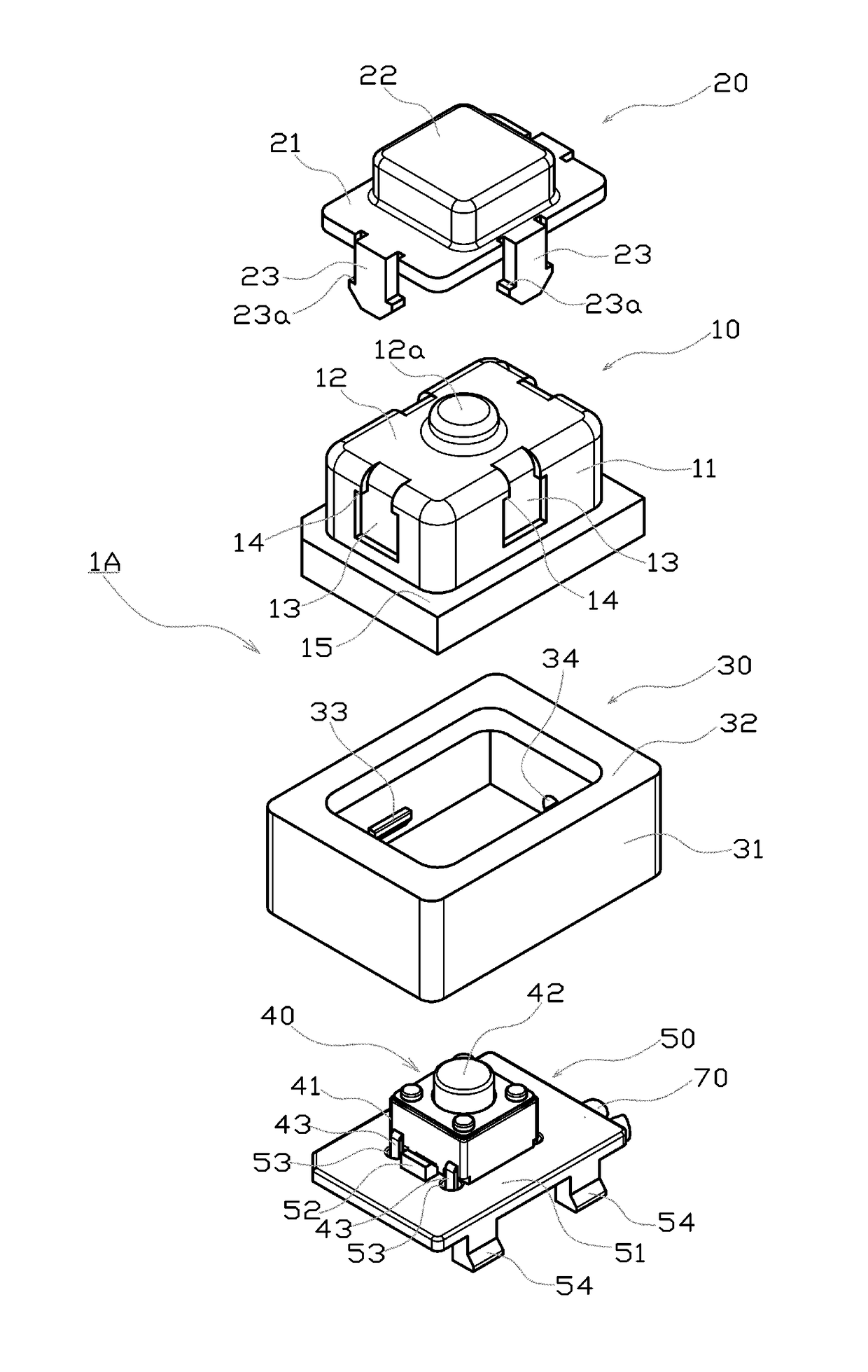
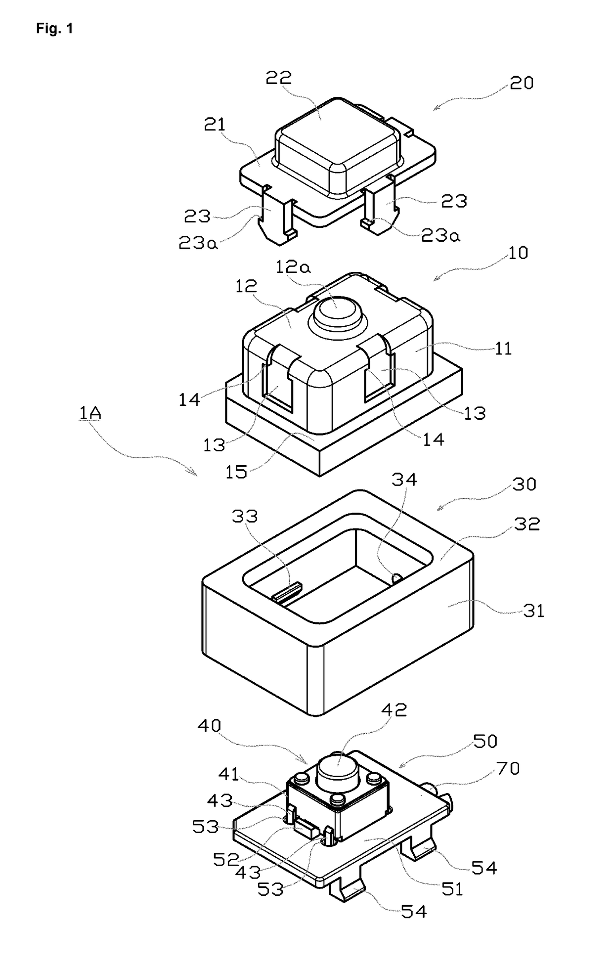
[0088]A push switch 1B according to a second exemplary mode of embodiment of the present invention will be described using FIG. 8 to FIG. 10.

[0089]In FIG. 8 to FIG. 10, constituent parts that are the same as in the first exemplary mode of embodiment are given the same reference numerals, and redundant description thereof is forgone.

[0090]In this example, the major differences with respect to the first exemplary mode of embodiment reside in the following two points.

[0091]First, in the first exemplary mode of embodiment, guide grooves 13 were formed on the four peripheral faces of the peripheral sidewall 11, which extended in the vertical direction, but in the push switch 1B of this example, guide grooves 113 are formed in two facing faces of the peripheral sidewall 11, and extend in the horizontal direction.

[0092]Furthermore, in the first exemplary mode of embodiment, the legs 23, which were somewhat elastic, extended from the four sides of the top ...


PUM


Abstract

Guide grooves are formed in a peripheral sidewall of a soft button, and a hard cap is separably connected to the button by fitting legs on the cap into these guide grooves. Furthermore, when a push-operation member on the cap is pushed, the legs are guided in the guide grooves, while the press stroke of the push-operation member is regulated by the bottom ends of the legs coming into contact with the top face of an inner flange on the case.

Description

BACKGROUND OF THE INVENTION[0001]The present invention relates to a push switch provided, for example, in a vehicle or the like.[0002]Japanese Patent Laid-Open Publication No. 2006-100013 describes a vehicle switch comprising a switch main body, which is held in an external member on the vehicle, and a button, which is provided in an opening in the external member, and is linked to the switch main body. In this vehicle switch, the button comprises a base made from a rubber material, which is provided in the opening in the external member, and linked to the switch main body, and a hard, decorative member, which covers the outside of the base.[0003]With the vehicle switch described in Japanese Patent Laid-Open Publication No. 2006-100013, the decorative member constitutes a part of the exterior design of the external member on the vehicle, and various types of decoration can be provided on the decorative member, allowing for more freedom in the decoration of the button and better desi...

Claims


Application Information

Patent Timeline
IPC IPC(8): H01H9/04H01H13/52
CPCH01H9/04H01H2231/026H01H13/52H01H13/06H01H13/14H01H9/06H01H2013/066H01H2221/052H01H2221/056
Inventor KITAHARA, TAKAHISA
Owner TOKYO PARTS IND CO LTD
Why Eureka
Try Eureka