Tuning of a kinematic relationship between members

a kinematic relationship and member technology, applied in the direction of asynchronous induction clutches/brakes, electric devices, transportation and packaging, etc., can solve the problem of asynchronous on-off switching of the braking effect, chatter becomes a hindrance, and chatter is particularly undesirable in some applications

Active Publication Date: 2017-08-17
EDDY CURRENT PARTNERSHIP
View PDF5 Cites 23 Cited by
  • Summary
  • Abstract
  • Description
  • Claims
  • Application Information

AI Technical Summary

Benefits of technology

[0027](a) prior to a sufficient energizing force, the at least one first member and at least one second member remain magnetically coupled and a first no or low induced eddy current brake effect occurs; and
[0028](b) on application of an energizing force sufficient to overcome the magnetically induced force, the at least one first member moves into the magnetic field thereby inducing an eddy current brake effect on movement of the at least one first member or a part thereof relative to the magnetic field.

Problems solved by technology

This can result is rapid on-off switching of the braking effect termed ‘chatter’.
Chatter in some applications is particularly undesirable.
Chatter becomes a hindrance in fall safety use.
For example, unwanted activation of the brake effect may occur when the person moves suddenly (but not a fall).
False activation may result in tiring the person; the person may loose balance and fall; or false activation simply becomes a general nuisance factor.
In worst cases, chatter may discourage use of the fall safety device and lead to serious injury or loss of life.

Method used


Image

  • Tuning of a kinematic relationship between members
  • Tuning of a kinematic relationship between members
  • Tuning of a kinematic relationship between members

Examples


working examples

[0133]The above described device is now described by reference to specific examples.

[0134]For ease of description in the examples, only a single first member is typically shown although it should be appreciated that multiple first members may be used.

[0135]A magnetic field through which the first member(s) move and third or latching member are generally shown for prolixity as continuous regions. The magnetic field, (if present at all) may for example be a series of discrete magnets or even just one magnet. Similarly, the third member (if present) may take on various shapes or surface contours, with only a limited number of examples shown for clarity.

[0136]While certain movement, for example of the first member(s) may be shown in an example, it should be appreciated that the magnetic field if present, the second member and / or the third member(s) may also move or even the first member remain fixed while the other member(s) move.

example 1

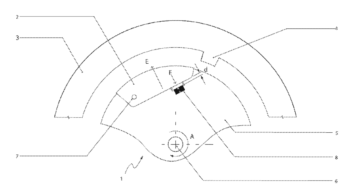
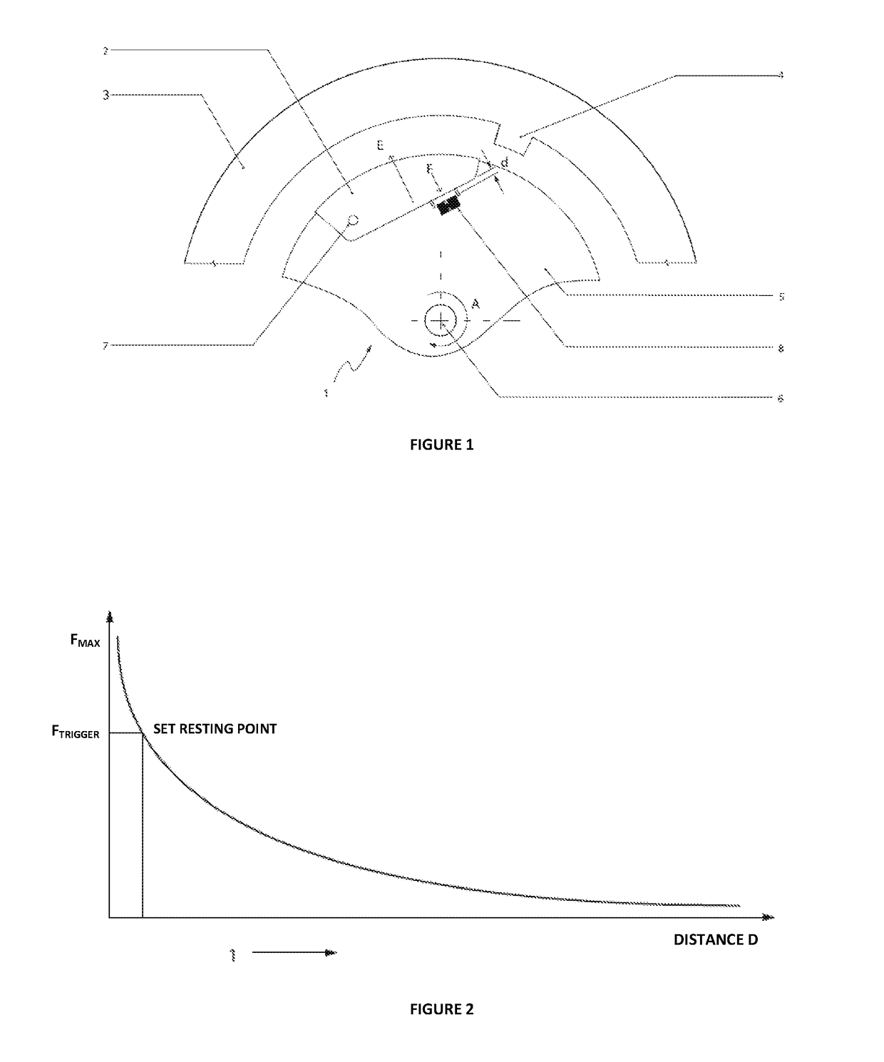
[0137]As illustrated by the schematic of FIG. 1, the device 1 in the embodiment shown comprises a first member 2 moving relative to a second member 5, in this example shown as being a rotor that rotates about rotor axis 6 in direction A. A third member 4 is also shown.

[0138]The first member 2 as shown is attached to the second member 5 and a kinematic relationship exists between the parts constrained by the first member pivot axis 7, the location of the third member 4 and the speed of rotation of the second member 5.

[0139]A magnetically induced force is in place between the first member 2 and the second member 5 via a magnet or magnets 8, in the Figure shown as being a block shape and linked to the second member 5. The first member 2 includes a portion 9 or as a whole is magnetically attracted to the magnet 8. The magnetically induced force prevents relative movement between the first member 2 and second member 5 until a threshold force F is exceeded by an energizing force E. In the...

example 2

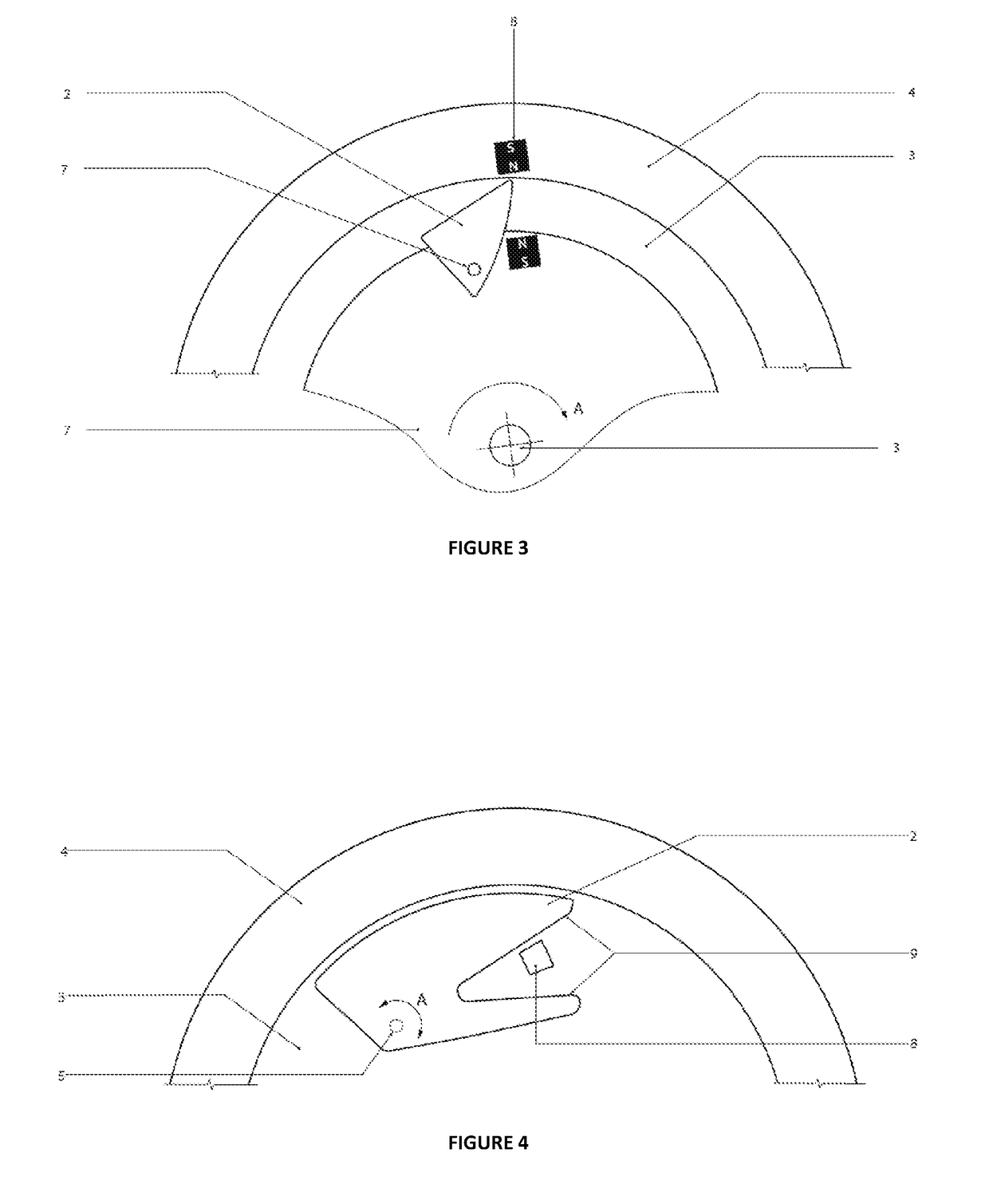
[0142]FIG. 3 illustrates an addition to the device of Example 1. In this example, a third member 4 is added, the third member 4 applying a magnetically induced force on the first member 2 thereby further changing the kinematic relationship between the various members 2, 4, 5. In the embodiment shown, a magnet is placed on the third member 4 that attracts a portion 9 or all of the first member 2. The induced force to the third member 4 is not sufficiently strong enough to overcome the induced force between the first member 2 and second member 5 until sufficient energizing force is applied (e.g., via rotation of the second member 5 about axis 6) to overcome the threshold force. When movement of the first member 2 starts to occur, the magnet on the third member 4 may then urge motion of the first member 2 to the third member 4. The magnet 10 on the third member 4 may also provide sufficient force to hold the first member 2 against the third member 4. A magnetic field 3 may lie adjacent...


PUM


Abstract

Described herein is a device comprising members in a kinematic relationship. The kinematic relationship is at least partially governed by at least one magnetically induced force that introduces a force threshold that, in effect, provides a threshold to part movement and confers a degree of hysteresis, preventing movement until a sufficiently large energizing force is applied. The effect may be further altered by use of an additional magnetically induced force interaction with at least one further member to urge or slow movement once started and/or to prevent movement once a new position is reached.

Description

RELATED APPLICATIONS[0001]This application derives priority from New Zealand patent application number 627630 incorporated herein by reference.BACKGROUND[0002]Technical Field[0003]Described herein is a device comprising members in a kinematic relationship, the kinematic relationship at least partially governed by at least one magnetically induced force that introduces a force threshold that, in effect, may provide a threshold and confer a degree of hysteresis, preventing movement until a sufficiently large energizing force is applied. The effect may be further altered by use of an additional magnetically induced force interaction with at least one further member to urge or slow movement once started and / or to prevent movement once a new position is reached.[0004]Description of the Related Art[0005]Eddy current formation may be used in a variety of ways to adjust the speed of rotation of a member. Various apparatus exist, for example in abseiling, to control the descent of a climber ...

Claims


Application Information

Patent Timeline
Patent Type & Authority Applications(United States)
IPC IPC(8): H02K7/104H02K7/10B60R22/343
CPCH02K7/104H02K7/10B60R22/343B60L7/28H02K49/04H02K2213/09B60L3/0007F16D43/14Y02T10/64H02K49/043H02K2213/06
Inventor DIEHL, ANDREW KARLALLINGTON, CHRISTOPHER JAMES
Owner EDDY CURRENT PARTNERSHIP
Why Eureka
Try Eureka