
Deckplate Auto Adjustment Mechanism for a Harvester Row Unit

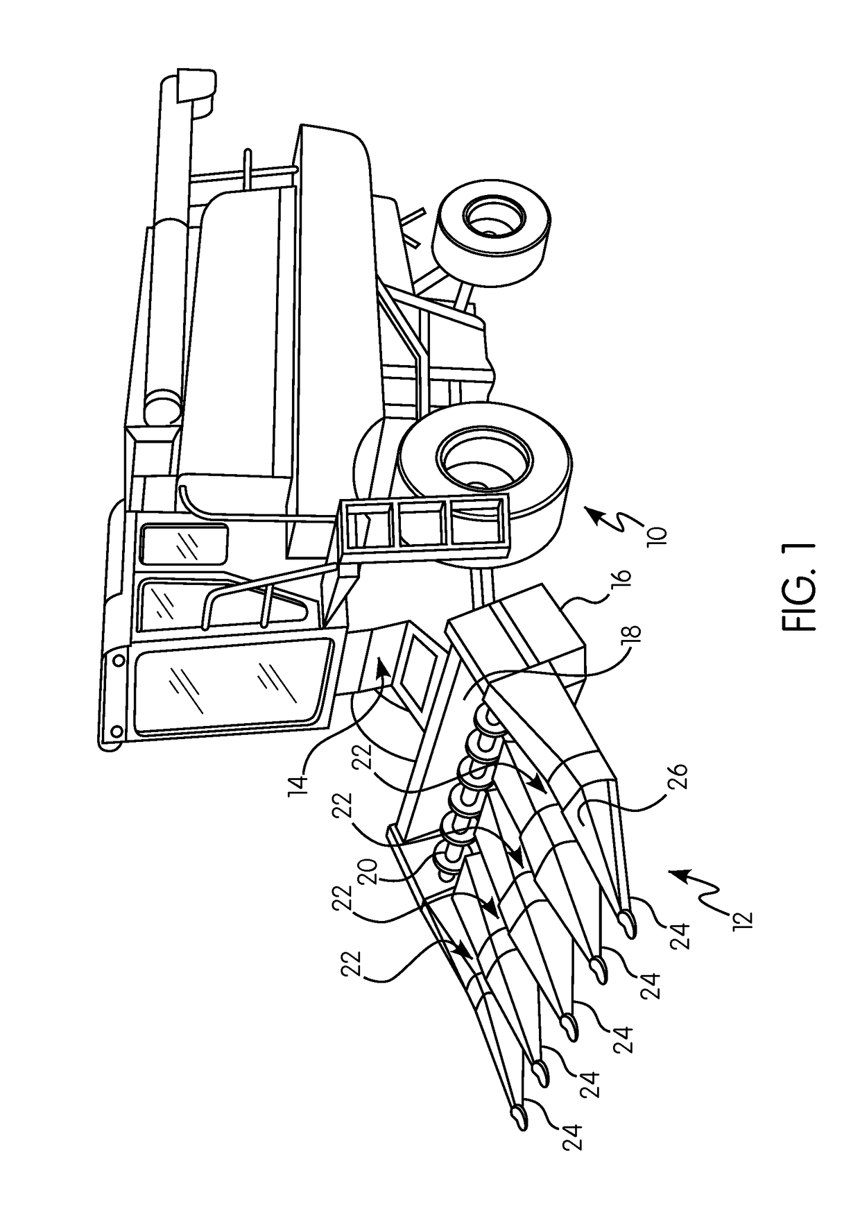
a technology of auto adjustment and harvester, which is applied in the direction of headers, agricultural tools and machines, agriculture, etc., can solve the problems of grain loss, ear damage and economic losses, and the operator's ability to properly set the deck plate,

Active Publication Date: 2017-08-24
BLUE LEAF I P
View PDF2 Cites 11 Cited by
  • Summary
  • Abstract
  • Description
  • Claims
  • Application Information

AI Technical Summary

Benefits of technology

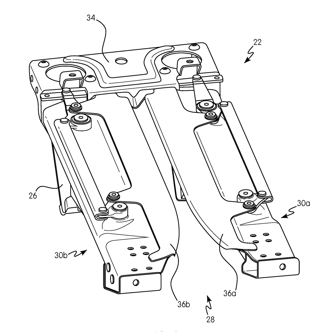
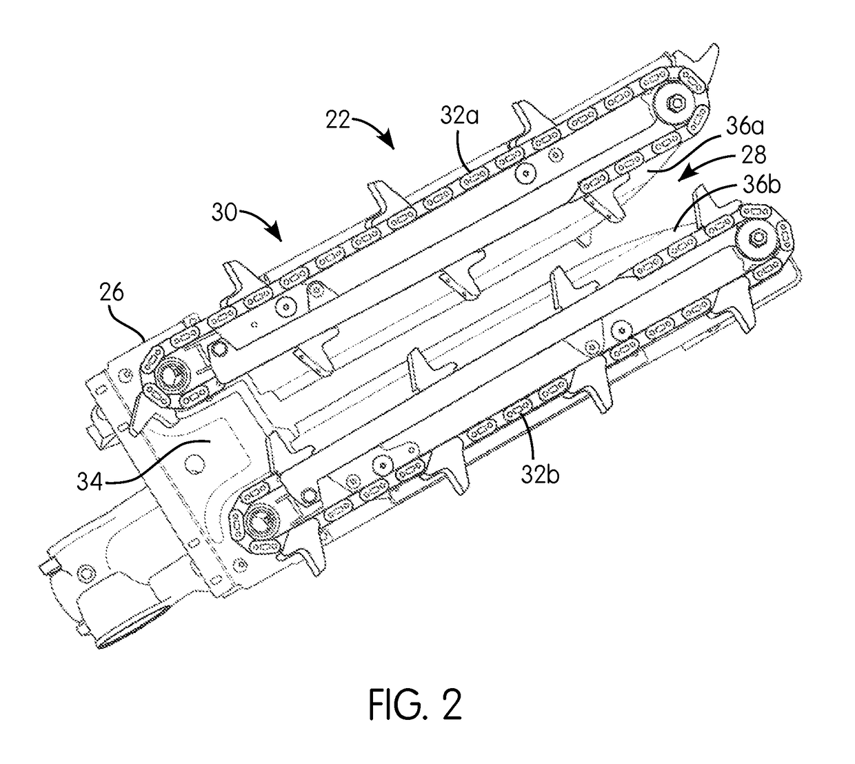
The patent text describes a row unit for an agricultural harvester that includes a gap adjustment mechanism and a deck plate assembly with multiple connection mechanisms. The gap adjustment mechanism allows for adjustment of the width of the gap between the deck plates, while the deck plate assembly ensures stability and resilience during operation. These features improve the performance and efficiency of the row unit, resulting in a more robust and reliable agricultural harvester.

Problems solved by technology

As a result, adjustment of the deck plate opening from row to row can be difficult, jerky and imprecise.
Mechanical tolerances which are built into such deck plate separation design in order to improve ease of deck plate movement also leads to backlash which affects the operator's ability to properly set the deck plates.
Improperly set or poorly adjusted deck plates cause grain loss, ear damage and economic losses.
Such designs are also bulky, heavy and take up valuable space underneath the corn header row unit.
Further, such designs can generate excess debris which can lead to trash accumulation under the corn header assembly effecting overall header efficiency and operation.
In addition, conventional rocker shaft control systems typically control only one of the two deck plates of a single row unit which can lead to the deck plate opening (or gap) not being aligned with the center of the row unit stalk rolls.

Method used


Image

  • Deckplate Auto Adjustment Mechanism for a Harvester Row Unit
  • Deckplate Auto Adjustment Mechanism for a Harvester Row Unit
  • Deckplate Auto Adjustment Mechanism for a Harvester Row Unit

Examples


Embodiment Construction

[0018]Reference will now be made in detail to the preferred embodiments of the invention illustrated in the accompanying drawings. Wherever possible, the same or like reference numbers will be used throughout the drawings to refer to the same or like features. It should be noted that the drawings are in simplified form and are not drawn to precise scale. In reference to the disclosure herein, for purposes of convenience and clarity only, directional terms such as top, bottom, above, below and diagonal, are used with respect to the accompanying drawings. Such directional terms used in conjunction with the following description of the drawings should not be construed to limit the scope of the invention in any manner not explicitly set forth. Additionally, the term “a,” as used in the specification, means “at least one.” The terminology includes the words above specifically mentioned, derivatives thereof, and words of similar import.

[0019]“About” as used herein when referring to a meas...


PUM


Abstract

A row unit for a header of an agricultural harvester is provided that includes a first longitudinally extending stripping plate and a second longitudinally extending stripping plate each mounted on a frame and each having opposed stripping edges which define a gap between the first stripping plate and the second stripping plate. The row unit includes both operator-selected macro adjustment of the gap and automatic micro adjustment of the gap. The micro adjustment occurs on both deck plates. The micro adjustment is achieved through resilient members positioned functionally between the deck plates and the row unit frame.

Description

BACKGROUND OF THE INVENTION[0001]The subject application relates generally to corn header assemblies for use with agricultural harvesters. In particular, the subject application relates to an improved corn header assembly that includes a deck plate auto adjustment mechanism.[0002]Agricultural harvesters that harvest corn are provided with headers having dividers, also generally known as snouts, for directing rows of corn stalks to row units that include ear separation mechanisms which include deck plates or stripping plates. The ears of corn are then passed to an auger for conveying the corn to a feeder house of the agricultural harvester. Thereafter harvested corn is then conveyed to the harvester's inner chambers for further processing.[0003]Conventional corn header assemblies use e.g., a rock shaft to control the separation or spacing of the deck plates (also referred to as the gap) within a row unit. Such deck plate separation designs have a rocker arm mounted vertically to the ...

Claims


Application Information

Patent Timeline
IPC IPC(8): A01D57/22A01D47/00A01D45/02
CPCA01D57/22A01D2101/00A01D47/00A01D45/023A01D45/021
Inventor GESSEL, JAMES M.COOK, JOELWALKER, ERICBERGGREN, MICHAELHUBACH, FREDCROW, BRIAN
Owner BLUE LEAF I P
Learn More