

Stretchable circuit board and method for manufacturing the same
a technology circuit boards, which is applied in the direction of flexible printed circuits, circuit bendability/stretchability, and insulating substrate metal adhesion improvement, etc., can solve the problems of difficult to employ a so-called one-side structure, limited substrate areas that form biological sensors, and no discussion of multi-layering of stretchable circuit boards
- Summary
- Abstract
- Description
- Claims
- Application Information
AI Technical Summary
Benefits of technology
Problems solved by technology
Method used
Image

Examples
first exemplary embodiment
[0032]Hereinbelow, a first exemplary embodiment according to the present invention will be described with reference to FIG. 1 and FIG. 2.
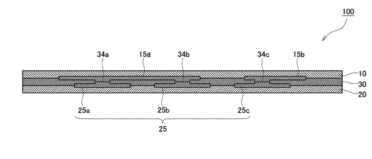
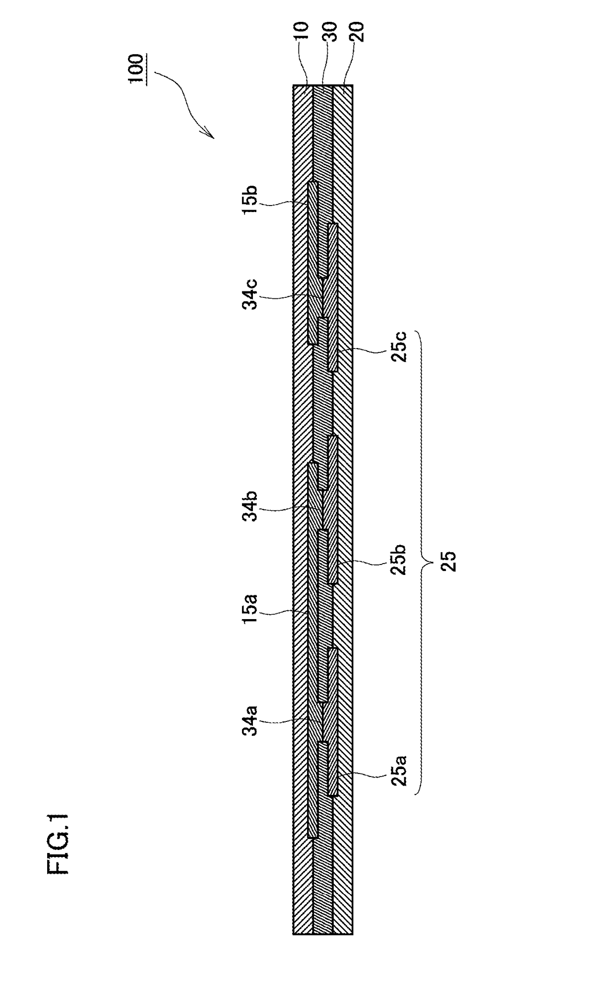
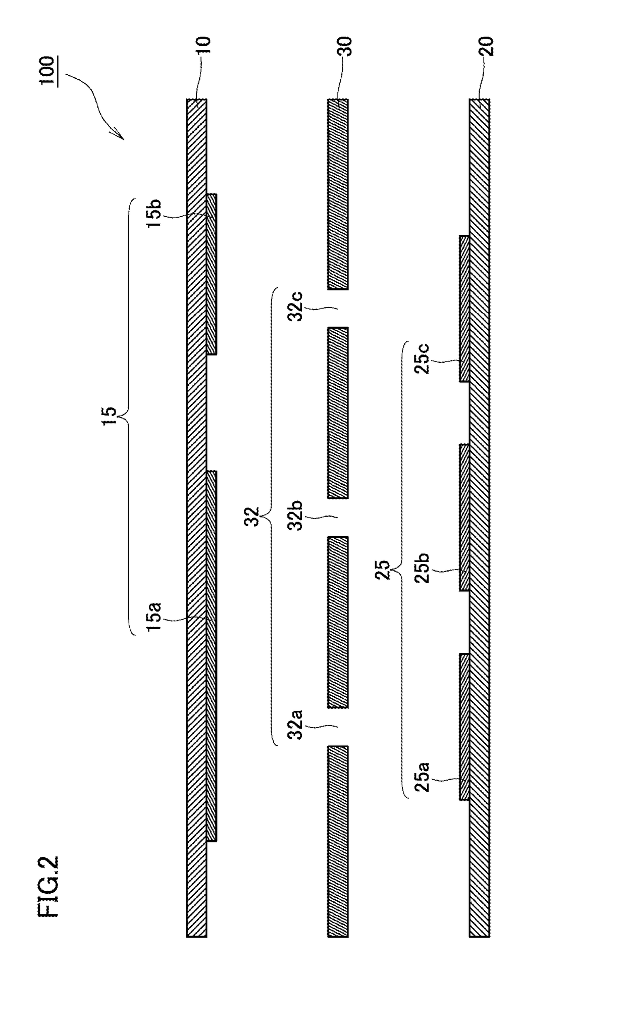
[0033]FIG. 1 is a sectional schematic view illustrating a stretchable circuit board 100 according to the first exemplary embodiment. FIG. 2 is an exploded schematic view illustrating the stretchable circuit board 100 according to the first exemplary embodiment. For the purpose of convenience, the upper side in FIG. 1 and FIG. 2 may be called the upper surface side, and the bottom side may be called the lower surface side. These directions, however, are defined for the purpose of convenience with the aim of illustrating relative positional relationships of constituent elements, and do not necessarily match the top or bottom in the gravity direction.
[0034]The stretchable circuit board 100 includes plural stretchable bases 10 and 20, and an interlayer stretchable base 30, and has a multi-layer structure with these bases being layered therein. Below, t...
second exemplary embodiment
[0071]Below, a stretchable circuit board 100 according to a second exemplary embodiment will be described with reference to FIG. 3 to FIG. 5. This description will be made with focus being placed on details specific to the second exemplary embodiment, and details that are the same as those in the first exemplary embodiment will not be repeated as appropriate.
[0072]FIG. 3 is a plan view illustrating the stretchable circuit board 100 according to the second exemplary embodiment when viewed from the upper surface side (from the upper side in FIG. 4). FIG. 4 is a sectional view taken along the line X-X in FIG. 3. FIG. 5 is an exploded schematic view of FIG. 4. For the purpose of convenience, the side away from a reader who is looking at FIG. 3 and the bottom side in FIG. 4 and FIG. 5 may be called the lower surface side, and the side toward the reader who is looking at FIG. 3 and the upper side in FIG. 4 and FIG. 5 may be called the upper surface side. These directions, however, are def...
third exemplary embodiment
[0112]Below, a stretchable circuit board 200 according to a third exemplary embodiment will be described with reference to FIG. 8 to FIG. 12. Note that, in the third exemplary embodiment, description will be made with focus being placed on details specific to the third exemplary embodiment, and details that are the same as those in the first exemplary embodiment and the second exemplary embodiment will not be repeated as appropriate.
[0113]FIG. 8 is a plan view illustrating the stretchable circuit board 200 according to the third exemplary embodiment when viewed from the side of the upper surface (from the upper direction in FIG. 8). FIG. 9 is an exploded perspective view illustrating the stretchable circuit board 200 illustrated in FIG. 8. FIG. 10 is a diagram for explaining a connecting portion 74 between a terminal portion 85 serving as a stretchable external terminal and a stretchable wiring portion 75 illustrated in FIG. 9. FIG. 11 is a sectional view taken along the line Y-Y of...
PUM
| Property | Measurement | Unit |
|---|---|---|
| Thickness | aaaaa | aaaaa |
| Pressure | aaaaa | aaaaa |
| Length | aaaaa | aaaaa |
Abstract
Description
Claims
Application Information