Sacroiliac Joint Stabilization And Fixation Devices And Related Methods

a technology for fixing devices and sacroiliac joints, applied in the field of joint fixation devices, can solve problems such as the risk of complications of traditional open surgical techniques for sacroiliac joint fusion, the reliance on screw thread fixation and/or a simple compression fit in the soft cancellous bon

Active Publication Date: 2017-09-14
WEST END BAY PARTNERS LLC
View PDF6 Cites 20 Cited by
  • Summary
  • Abstract
  • Description
  • Claims
  • Application Information

AI Technical Summary

Benefits of technology

The method described in this patent allows for an engaged device (like a lock) to be disengaged by moving one part of it out of the way. This makes it easier to release or activate another component without having to fully detach them first.

Problems solved by technology

The technical problem addressed in this patent text is the need for improved sacroiliac joint stabilization fixation devices that provide better long-term compression of the joint space. Current devices rely on screw thread fixation or a simple compression fit in the soft cancellous bone of the sacrum, which can lead to complications.

Method used


Image

  • Sacroiliac Joint Stabilization And Fixation Devices And Related Methods
  • Sacroiliac Joint Stabilization And Fixation Devices And Related Methods
  • Sacroiliac Joint Stabilization And Fixation Devices And Related Methods

Examples


Embodiment Construction

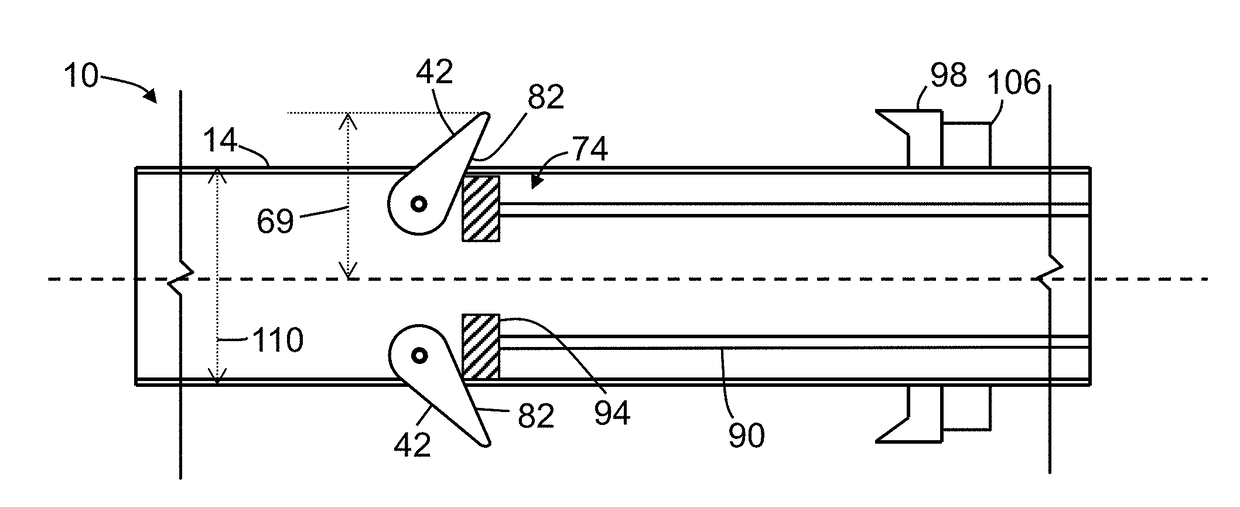
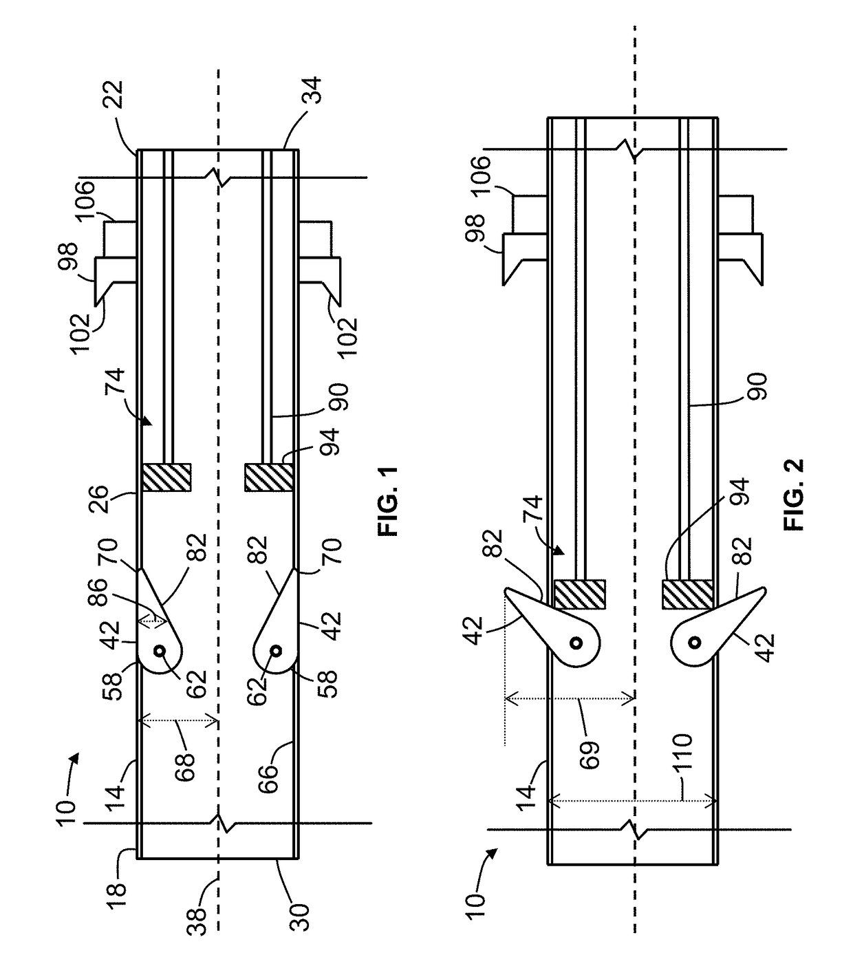
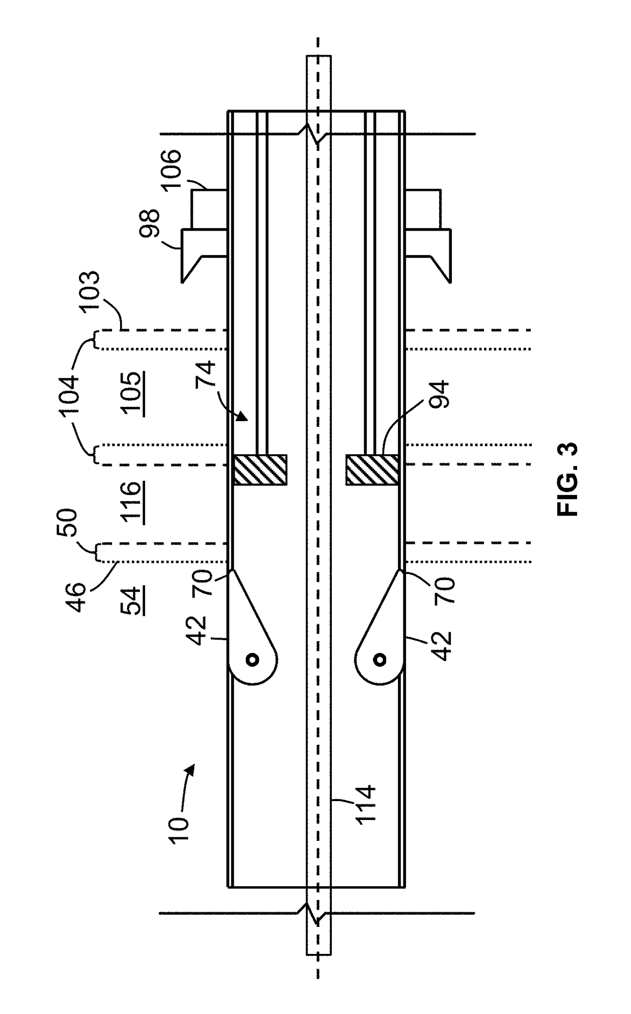
[0067]Referring now to the drawings, and more particularly to FIGS. 1-4, shown therein and designated by the reference numeral 10 is one embodiment of the present anchor devices. In the embodiment shown, device 10 includes an elongated housing 14 (e.g., a housing) having a first end 18, a second end 22, and a midsection 26 extending between the first end and the second end. As shown, housing 14 may include a first opening 30 at first end 18 and a second opening 34 at second end 22. Housing 14 may be characterized by and described relative to a longitudinal axis 38 extending along a length of midsection 26.

[0068]In the embodiment shown, for example, in FIGS. 1-4, housing 14 may include one or more engagement members 42 (e.g., two engagement members, as shown) movable between a retracted position and an extended position, in which the engagement member is configured to securely engage an inner surface 46 of a cortical wall 50 (“sacral cortical wall”) of a sacrum bone 54. More particul...


PUM


Abstract

An anchor device for use in sacroiliac joint stabilization comprises a housing having a bore, one or more apertures, and a threaded outer surface, one or more engagement members at least partially disposed in the housing, where at least one of the one or more engagement members is movable between a retracted position and an extended position such that, when the at least one of the one or more engagement members is in the extended position, the at least one of the one or more engagement members extends through at least one of the one or more apertures, and where, when the at least one of the one or more engagement members is in the extended position, the at least one of the one or more engagement members is configured to engage a cortical wall of a sacrum bone.

Description


Claims


Application Information

Patent Timeline
Owner WEST END BAY PARTNERS LLC
Why Eureka
Try Eureka