Instrumentation for fusing a sacroiliac joint

a technology for fusion instruments and sacroiliac joints, which is applied in the field of system and instrumentation for fusion of sacroiliac joints, can solve the problems of complex devices, si joint dysfunction, and pain in the si joint properly functioning

Active Publication Date: 2021-10-26
View PDF154 Cites 2 Cited by
  • Summary
  • Abstract
  • Description
  • Claims
  • Application Information

AI Technical Summary

Problems solved by technology

Dysfunction in the SI Joint is a common problem of back pain.
Even a properly functioning SI Joint can become painful after certain types of spinal procedures.
These procedures involve complex devices, such as drills and drill bits, and multi-component dilators, braces, and anchor installation devices.
As a result, fusion procedures using these devices are complex and time consuming, often leading to suboptimal results.
Another complication of SI Joint fusion is that promoting bone fusion often involves decorticating the cortical bone inside the SI Joint.
These abrading devices often become lodged inside the SI Joint during the decortication process.
When the abrading device becomes lodged, counter pressure cannot be applied to the patient to counteract the pull-out force needed to dislodge the abrading device.
Any such counter pressure applied to the patient could result in injury to the patient or damage to surrounding tissue.
However, past slide hammer assemblies are cumbersome to operate, difficult to attach to the abrading device, and difficult to operate.
They also complicate the instrumentation needed to perform the SI Joint fusion procedure.

Method used


Image

  • Instrumentation for fusing a sacroiliac joint
  • Instrumentation for fusing a sacroiliac joint
  • Instrumentation for fusing a sacroiliac joint

Examples


Embodiment Construction

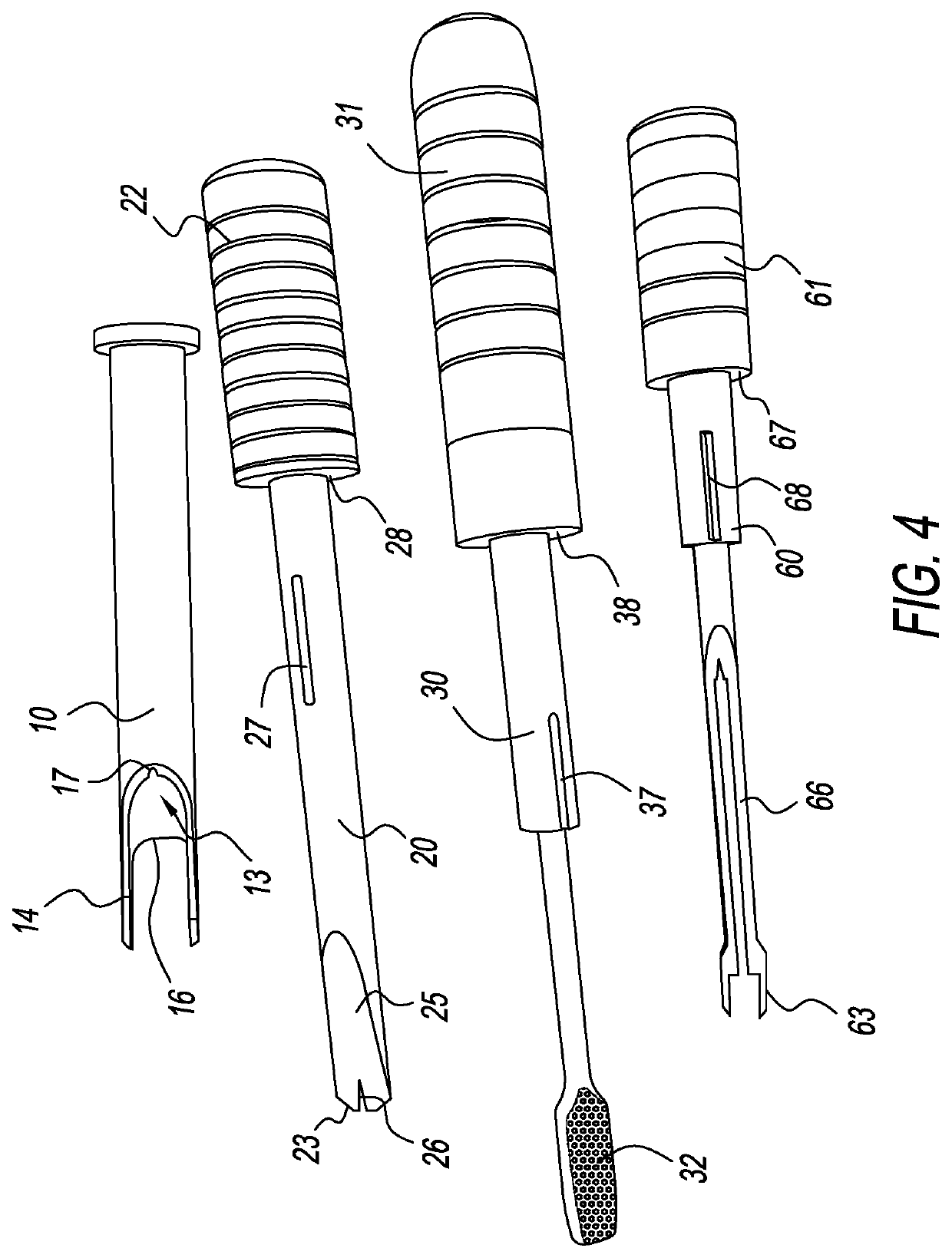
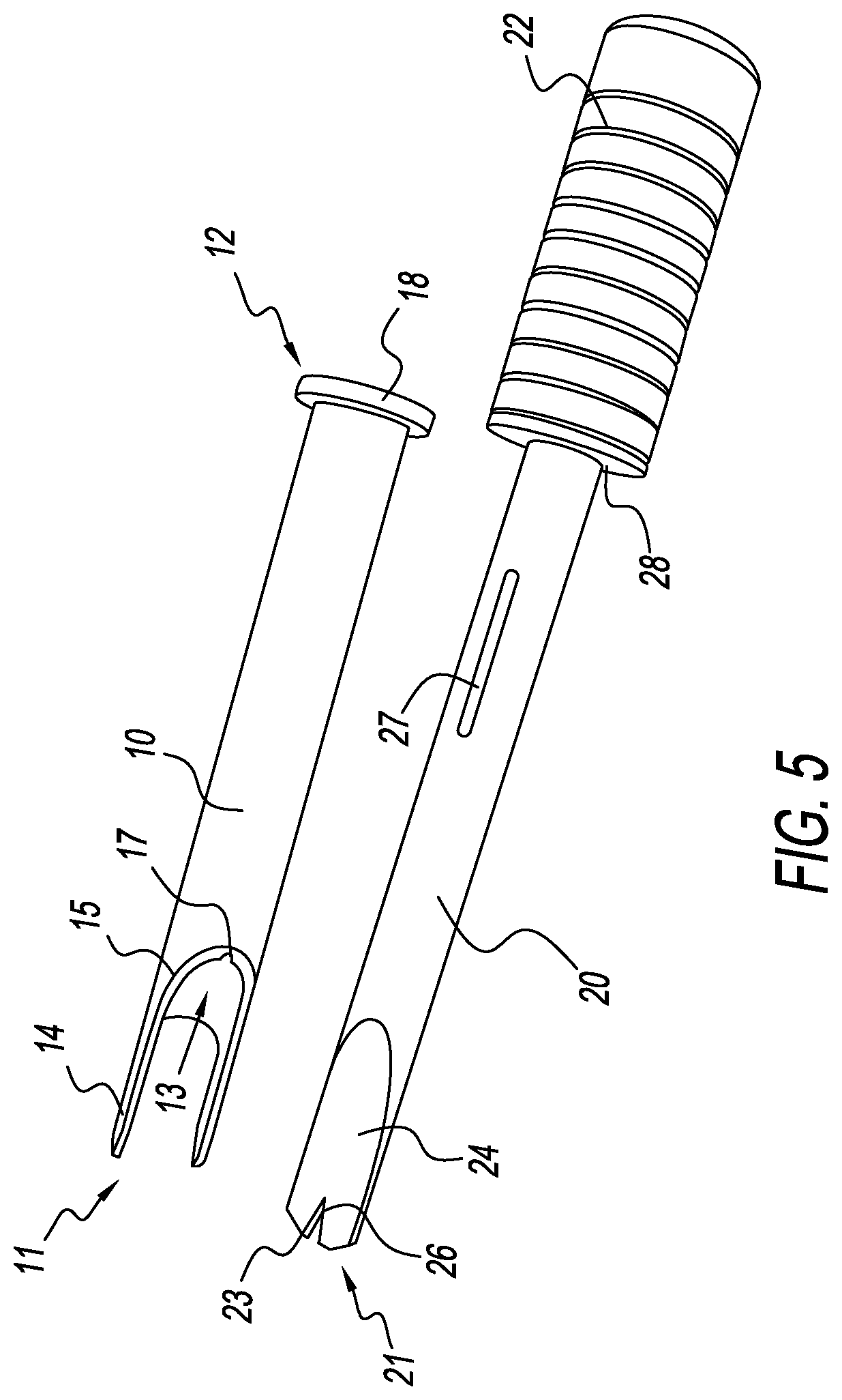
[0008]In the preferred embodiment, the system and instrumentation described herein comprises a working channel, a joint locator, an abrading device, and an implant inserter. The working channel has an insertion end and a working end, and a channel extending therebetween. The working channel provides a working passage for insertion of the other instruments of the system, and for delivery of the implant to the SI Joint. The insertion end has a pair of arms for providing engagement of the SI Joint and distraction of tissue surrounding the insertion end. The insertion end further comprises a first iliac contour and a first sacral contour, both of which are defined by the contour between the insertion arms and the body of the working channel. The inside surface of the working channel has an alignment means comprising a groove, recess, channel, indent, or the like for receiving and engaging a ridge, rib, detent, or other protrusion on the mating instrument that is keyed to the alignment m...


PUM


Abstract

An apparatus for installing a fusion implant into the sacroiliac joint (“SI Joint”). The apparatus comprises a working channel, a joint locator, an abrading device, and an insertion device. The joint locator is inserted into the working channel, and this combination, guided by a K-wire, is advanced into the SI Joint. The joint locator is removed, and the abrading device is used to abrade the sacrum and ilium inside the SI Joint. The insertion device then advances the implant into the abraded area of the SI Joint. The abraded area heals across the implant, thereby fusing the sacrum to the ilium and fusing the SI Joint.

Description

CROSS-REFERENCE TO RELATED APPLICATION[0001]Pursuant to 35 U.S.C. § 119(e), this application claims the benefit of U.S. Provisional Patent Application Ser. No. 62 / 910,913, filed on Oct. 4, 2019, the entire contents of which are incorporated herein by this reference.BACKGROUND(1) Field of Endeavor[0002]The present invention relates generally to the field of sacroiliac joint fusion procedures, and more particularly, to a unique system and instrumentation for fusing a sacroiliac joint.(2) Description of Related Art[0003]The sacroiliac joint (“SI Joint”) is located at the interface between the sacrum and ilium bones in a human's pelvic area. The SI Joint includes strong ligaments that permit only slight movement between the sacrum and the ilium. The sacrum is connected to the base of the spine, and each ilium is connected to the top of the leg and hip area. Thus, the SI Joint is the interface between a human's upper body and lower body.[0004]Dysfunction in the SI Joint is a common probl...

Claims


Application Information

Patent Timeline
Patent Type & Authority Patents(United States)
IPC IPC(8): A61F2/46A61B17/16A61B17/02A61F2/30A61B17/84A61B17/92A61B17/90
CPCA61F2/30988A61B17/848A61B17/92A61F2/4611A61B2017/90A61B2017/922A61F2002/30995A61F2002/30261A61F2002/30593A61F2002/30827A61F2002/30904A61F2002/4625A61F2002/4627A61F2002/4681A61F2002/30622A61B17/1671A61B17/1659A61F2/4455A61F2/447A61F2002/30785A61F2002/30828A61F2002/4622A61B17/90
Inventor LANEVE, SEANGIRSCH, CHARLESGIRSCH, CHRIS
Why Eureka
Try Eureka