As is also well established, the noted loads and, hence, forces exerted on the SI joint can adversely affect the biomechanical functions of the SI joint, which can, and often will, result in SI joint dysfunction—an often-overlooked musculoskeletal
pathology associated with lower
back pain.
However, lower
back pain associated with SI joint dysfunction is suspected to be far more common than most healthcare providers realize, since such pain is often associated with other skeletal and musculoskeletal dysfunctions.
Although several conventional SI joint stabilization
surgical methods and associated bone prostheses have effectively ameliorated pain associated with SI joint dysfunction, there remains many disadvantages associated with the conventional
surgical methods and associated SI joint prostheses.
A major
disadvantage associated with many conventional SI joint stabilization
surgical methods is that the surgeon is required to make a substantial incision in and through the
skin and tissues of a subject to access the dysfunctional SI joint.
Although conventional minimally-invasive SI joint stabilization systems and methods, such as the systems and methods disclosed in U.S. Pub. No. 2009 / 0076551 to Petersen, have garnered some success in relieving pain associated with SI joint dysfunction and have effectively addressed many of the disadvantages associated with
open surgery systems and methods, there similarly remains many disadvantages associated with conventional minimally-invasive SI joint stabilization systems and methods.
Despite the level of
surgical training and experience that surgeons possess, when such conventional minimally-invasive SI joint stabilization systems and methods are employed, there is still a substantial incidence of damage to the lumbosacral neurovascular structures
proximate to the SI joint.
Further disadvantages associated with many conventional minimally-invasive SI joint stabilization systems and methods are that
visualization of the SI joint after creation of a pilot opening for the SI joint prostheses is restricted and arthrodesis of the SI
joint bone structures, i.e., ilium and
sacrum, is often suboptimal.
A further
disadvantage associated with many conventional minimally-invasive SI joint stabilization systems, methods, and associated apparatus, i.e., SI joint prostheses, such as the systems, methods, and joint stabilization prostheses disclosed in U.S. Pub. No. 2009 / 0076551 to Petersen, is that pre-existing sacral abnormalities can lead to displacement of the implanted prostheses, which can, and often will result in damage to surrounding bone and
soft tissue structures.
An additional disadvantage associated with many conventional minimally invasive SI joint stabilization systems and methods is that they comprise anterior or lateral approaches to the dysfunctional SI joint and, hence, muscles, e.g., gluteal aponeurotic
fascia and gluteus
medius, and ligaments are typically disrupted, and nerves and blood vessels are susceptible to damage during placement of a
prosthesis in a dysfunctional SI joint.
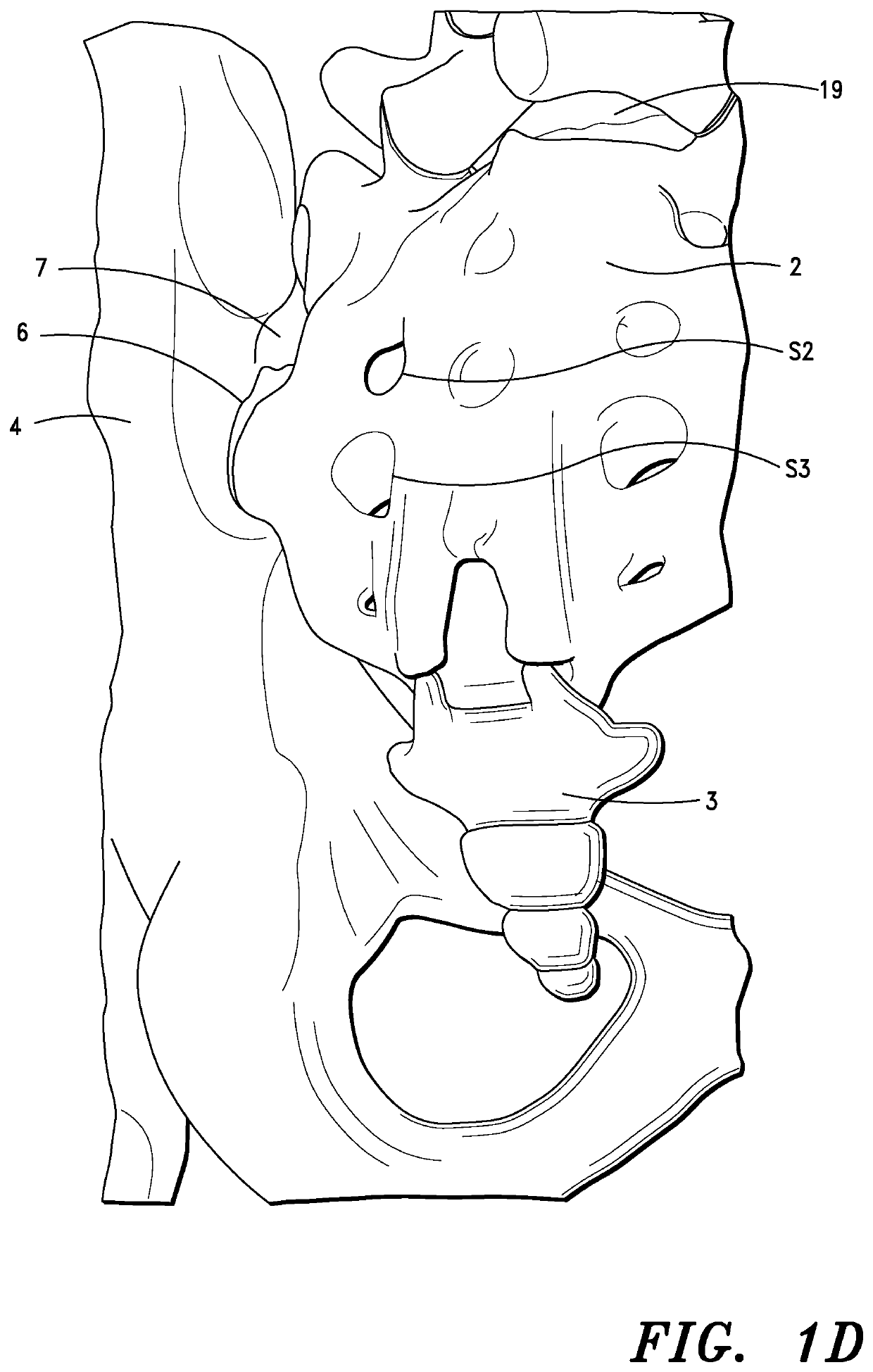
Further, some conventional minimally-invasive SI joint
stabilization methods are particularly prone to failure due to displacement of the SI joint prostheses in the dysfunctional SI joint, such as in or
proximate the SI joint dorsal recess referenced above and shown in FIG. 1D, and / or failure of the prostheses to effectively engage the SI joint structures, e.g.,
articular surfaces of the
sacrum and / or ilium.
Although many of the “improved” SI joint prostheses, when deployed properly in a dysfunctional SI joint, can, and often will, effectively engage SI joint structures, there remains several disadvantages associated with the prostheses.
A major disadvantage associated with the noted SI joint prostheses is that the liquefiable synthetic polymers, when re-solidified in situ, are structurally inferior to the osseous or
bone tissue of the sacrum and ilium.
The fusion sites between the
articular surfaces of the sacrum and ilium that define the SI joint are, thus, highly susceptible to
structural fatigue and failure, which can, and often will, result in misalignment of the SI joint and ultimately increased pain for the subject.
A further disadvantage associated with the SI joint prostheses disclosed in U.S. Pat. No. 8,951,254 is that the synthetic liquefiable synthetic polymers are also substantially immunogenic and will induce an adverse immune response when the prostheses are implanted in a dysfunctional SI joint.

