
Systems and methods for determining a sustained thermal power envelope comprising multiple heat sources

a technology of sustained thermal power envelope and heat source, applied in the field of systems and methods, can solve the problems of pcds affecting user qos, pcds affecting user experience, and rare space within pcds for engineers and designers

Active Publication Date: 2017-09-14
QUALCOMM INC
View PDF6 Cites 16 Cited by
  • Summary
  • Abstract
  • Description
  • Claims
  • Application Information

AI Technical Summary

Problems solved by technology

As such, there rarely is enough space within a PCD for engineers and designers to mitigate thermal degradation or failure of processing components by using clever spatial arrangements or strategic placement of passive cooling components.
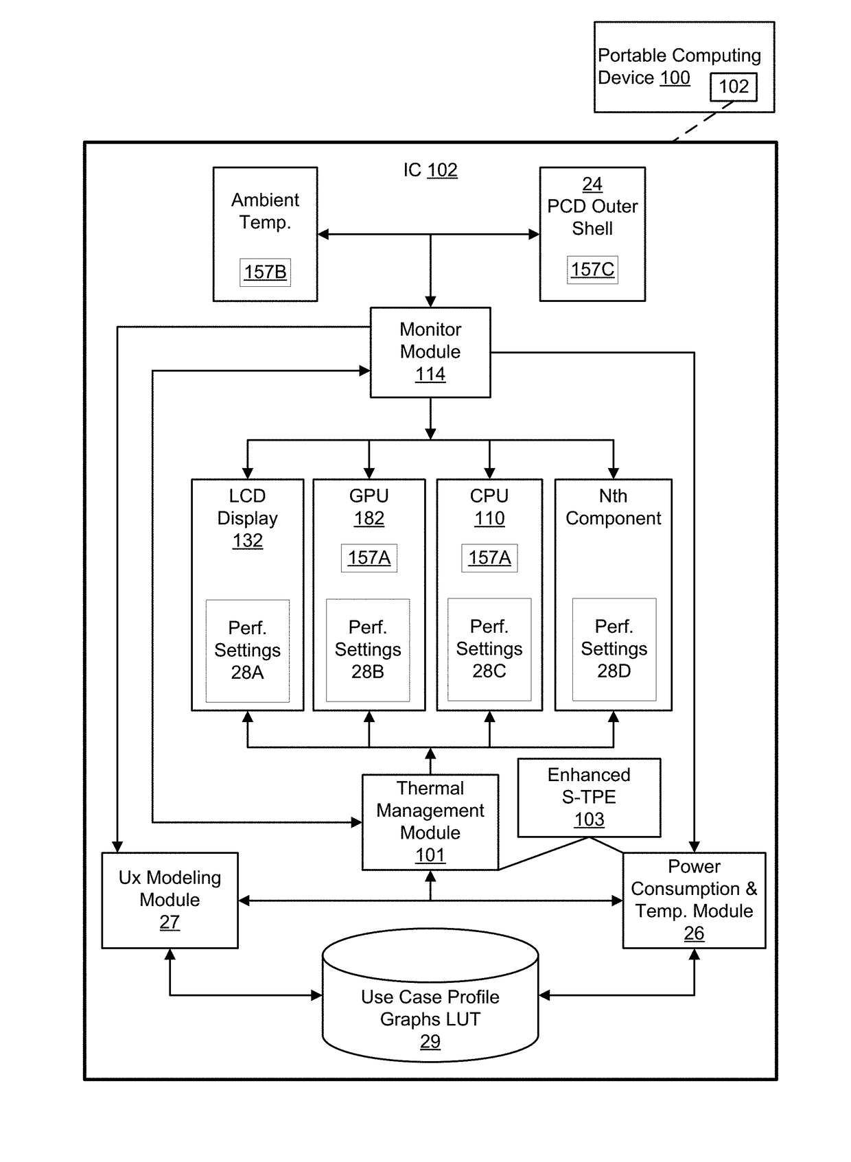
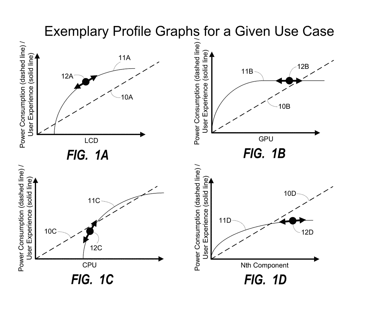
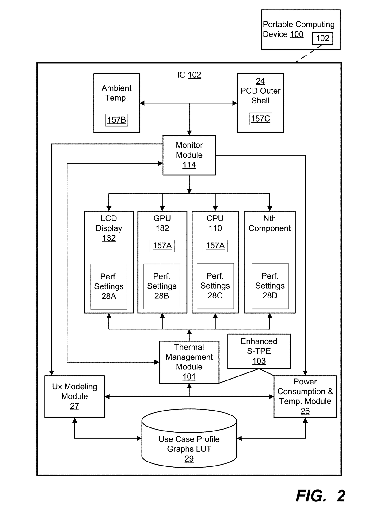
For example, under a heavy processing workload associated with a gaming use case, current systems and methods throttle the voltage and frequency of multiple components to remain within an overall power budget that precludes excessive thermal energy generation.
That is, throttling the multiple components in a “one size fits all” manner accomplishes the goal of staying within the power budget constraints (thereby reducing thermal energy generation), but causes the user experience to suffer due to throttling components that have minimal impact on the problematic thermal energy generation.
As such, current systems and methods for mitigating excessive thermal energy generation by processing components in a PCD may unnecessarily impact the QoS provided to a user.
Problems may arise when a conventional S-TPE is used as a benchmark for the device in all situations.
For example, when significant heat is contributed by a component other than that used for S-TPE collection, the S-TPE may diverge from the use case measurements in noticeable and unexpected ways.
For the same reason, existing methods for collecting S-TPE may produce results that are inconsistent and difficult to compare across several collection attempts.

Method used


Image

  • Systems and methods for determining a sustained thermal power envelope comprising multiple heat sources
  • Systems and methods for determining a sustained thermal power envelope comprising multiple heat sources
  • Systems and methods for determining a sustained thermal power envelope comprising multiple heat sources

Examples


Embodiment Construction

[0025]The word “exemplary” is used herein to mean “serving as an example, instance, or illustration.” Any aspect described herein as “exemplary” is not necessarily to be construed as exclusive, preferred or advantageous over other aspects.

[0026]In this description, the term “application” may also include files having executable content, such as: object code, scripts, byte code, markup language files, and patches. In addition, an “application” referred to herein, may also include files that are not executable in nature, such as documents that may need to be opened or other data files that need to be accessed.

[0027]As used in this description, the terms “component,”“database,”“module,”“system,”“thermal energy generating component,”“processing component” and the like are intended to refer to a computer-related entity, either hardware, firmware, a combination of hardware and software, software, or software in execution. For example, a component may be, but is not limited to being, a pro...


PUM


Abstract

Various embodiments of systems and methods are disclosed for determining a thermal power envelope. One method comprises determining a set of component and operating point combinations for a plurality of components in a portable computing device. Each component and operating point combination in the set defines an available operating point for each of the plurality of components. The portable computing device is iteratively set to each of the component and operating point combinations in the set. At each of the component and operating point combinations, power consumption data and skin temperature data is collected from a plurality of temperature sensors. An enhanced thermal power envelope is generated comprising the power consumption data and the skin temperature data for each of the component and operating point combinations.

Description

PRIORITY CLAIM AND RELATED APPLICATION[0001]This application claims priority under 35 U.S.C. §119(e) to U.S. Provisional Application Ser. No. 62 / 305,341, filed on Mar. 8, 2016, entitled, “SYSTEMS AND METHODS FOR DETERMINING A SUSTAINED THERMAL POWER ENVELOPE COMPRISING MULTIPLE HEAT SOURCES,” the entire contents of which are hereby incorporated by reference.DESCRIPTION OF THE RELATED ART[0002]Portable computing devices (“PCDs”) are becoming necessities for people on personal and professional levels. These devices may include cellular telephones, portable digital assistants (“PDAs”), portable game consoles, palmtop computers, and other portable electronic devices.[0003]One unique aspect of PCDs is that they typically do not have active cooling devices, like fans, which are often found in larger computing devices such as laptop and desktop computers. Instead of using fans, PCDs may rely on the spatial arrangement of electronic packaging so that two or more active and heat producing co...

Claims


Application Information

Patent Timeline
Patent Type & Authority Applications(United States)
IPC IPC(8): G06F1/26G06F1/32
CPCG06F1/3206G06F1/26G06F1/20Y02D10/00
Inventor LEE, KWANGYOONWAN, KAI YEECUNNINGHAM, ADAMOCLIMA, MELANIE DOLORES
Owner QUALCOMM INC
Learn More