Projection apparatus, image processing apparatus, and image processing method
a technology of projection apparatus and projection apparatus, applied in the direction of nmr measurement, instruments, television systems, etc., can solve the problems of reducing the accuracy of coordinate transformation, affecting the quality of images, and affecting the accuracy of projection apparatus
- Summary
- Abstract
- Description
- Claims
- Application Information
AI Technical Summary
Benefits of technology
Problems solved by technology
Method used
Image
Examples
first embodiment
Apparatus Arrangement
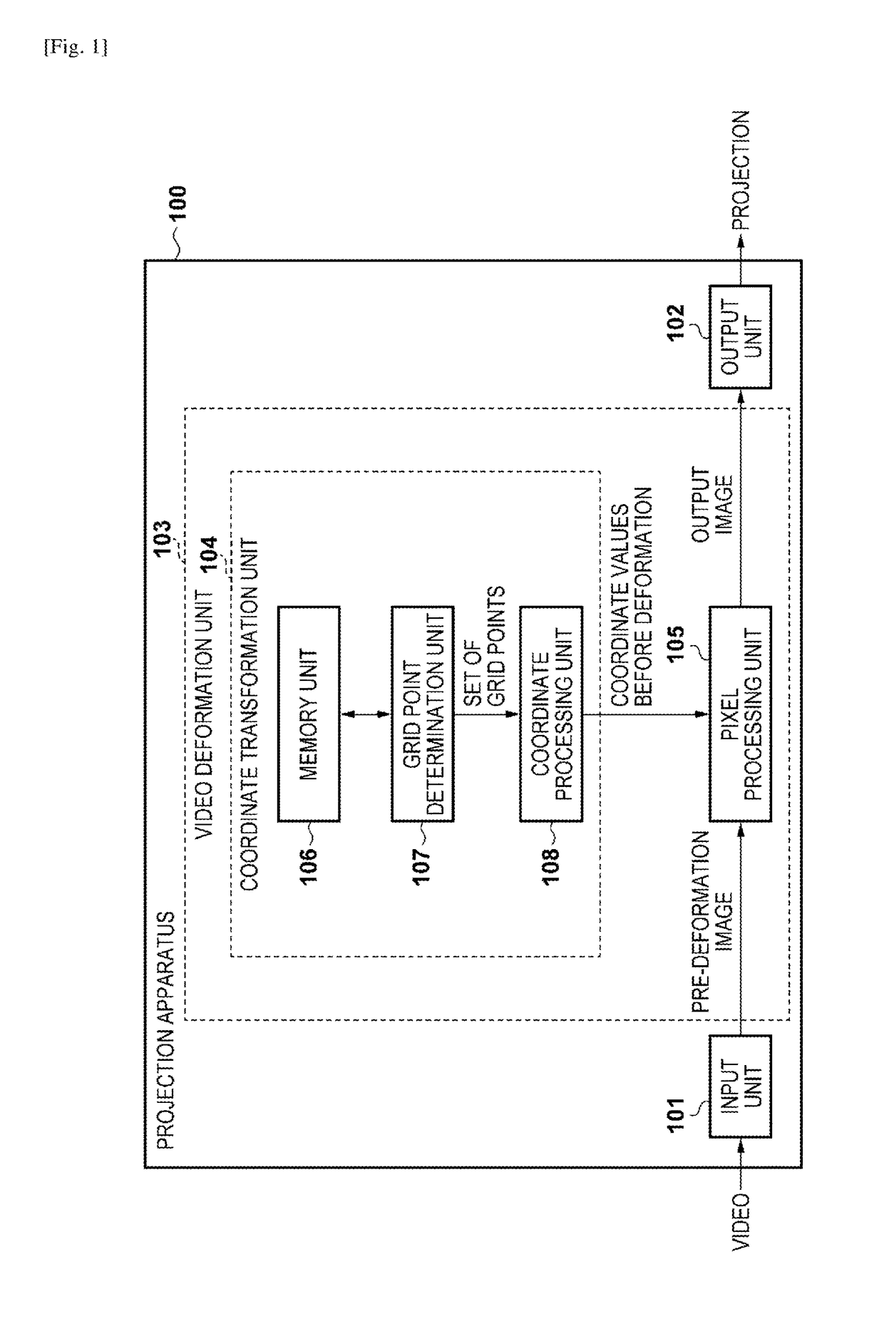
[0028]The arrangement of a projection apparatus 100 according to the first embodiment is shown in the block diagram of FIG. 1. The projection apparatus 100 comprises an input unit 101 that inputs a video, a video deformation unit 103 that performs image processing on the input video to deform the video, and an output unit 102 that projects the deformed video.
[0029]The video deformation unit 103 comprises a coordinate transformation unit 104 that calculates the coordinate values of a pixel of interest before deformation, and a pixel processing unit 105 that calculates the pixel value of the pixel of interest from the coordinate values of the pixel of interest before deformation and a pre-deformation image. The video deformation unit 103 executes image deformation processing as image processing in the projection apparatus 100.
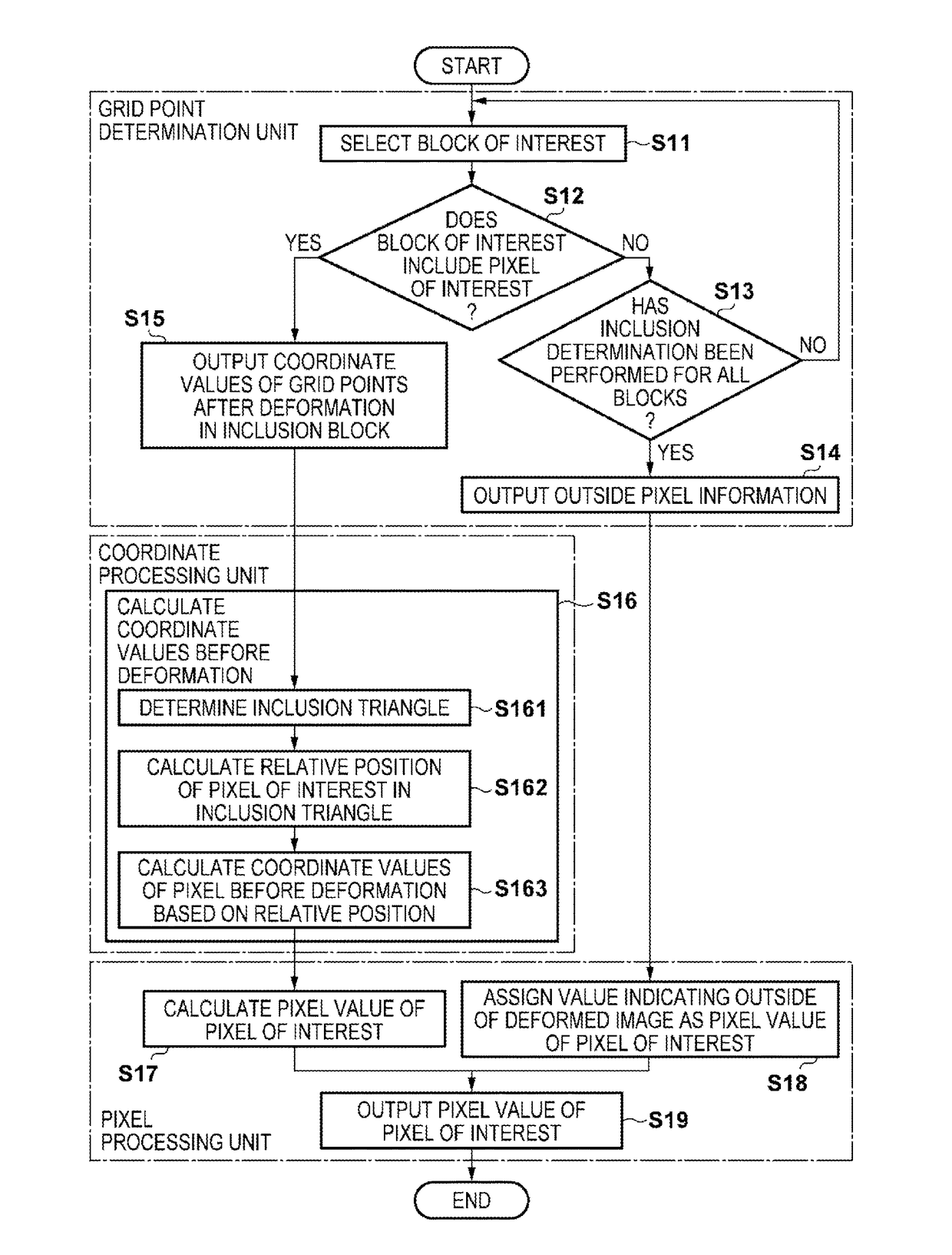
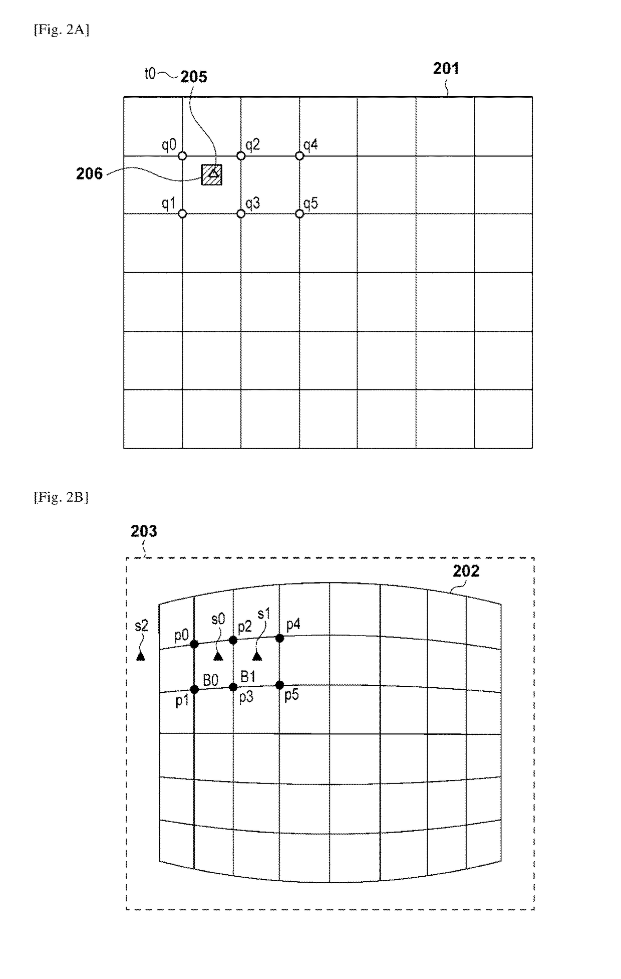
[0030]The coordinate transformation unit 104 comprises a memory unit 106 that stores grid points after deformation, a grid point determinati...
second embodiment
[0052]A projection apparatus, an image processing apparatus, and an image processing method according to the second embodiment of the present invention will be described below. In the second embodiment, the same reference numerals as those in the first embodiment denote the same parts, and a detailed description thereof will not be repeated in some cases.
[0053]The first embodiment has explained an example of the arrangement in which blocks are unconditionally set as inclusion determination targets until an inclusion block is detected, in order to determine a set of grid points p after deformation to be used for coordinate transformation of a pixel of interest. According to this inclusion determination target block decision method, an inclusion block may be detected by a small number of times, or a final block may be detected as an inclusion block by performing the inclusion determination for all blocks. Further, when a pixel of interest exists outside the deformed image 202, the inc...
embodiments
Modification of Embodiments
[0068]The second embodiment has explained an example in which the inclusion determination target block is determined using an immediately preceding pixel of interest as a reference. However, it is only necessary to determine an inclusion determination target block by using, as a reference, a pixel having undergone inclusion determination that is adjacent to the top, bottom, left, or right of a pixel of interest or obliquely adjacent to it. For example, the grid point determination unit 107 holds information of the inclusion block of pixels of one line in the lateral direction, and sets, as the center of the inclusion determination target block, the inclusion block (to be referred to as a “previous inclusion block” hereinafter) of a pixel adjacent to a pixel of interest in the upper direction or upper oblique direction.
[0069]The second embodiment has explained an example in which the number of inclusion determination target blocks changes at the end portion...
PUM
 Abstract
Description
Claims
Application Information
 - R&D
- Intellectual Property
- Life Sciences
- Materials
- Tech Scout
- Unparalleled Data Quality
- Higher Quality Content
- 60% Fewer Hallucinations
Browse by: Latest US Patents, China's latest patents, Technical Efficacy Thesaurus, Application Domain, Technology Topic, Popular Technical Reports.
© 2025 PatSnap. All rights reserved.Legal|Privacy policy|Modern Slavery Act Transparency Statement|Sitemap|About US| Contact US: help@patsnap.com


