Flood protection for underground air vents

a technology for underground air vents and flood protection, which is applied in ventilation systems, heating types, shutters/movable grilles, etc., can solve the problems of sacrificing the available sidewalk area for pedestrians, not only costing a lot of money to implement, and storm sewers are overwhelmed

Active Publication Date: 2017-11-02
FLOODBREAK
View PDF0 Cites 5 Cited by
  • Summary
  • Abstract
  • Description
  • Claims
  • Application Information

AI Technical Summary

Benefits of technology

The patent text describes a solution for preventing flooding water from entering underground ventilation passages, which can occur during heavy rains or snowstorms. The solution involves using panels that can be raised to block the openings of the ventilation ducts, reducing the amount of water that enters the system. The panels are designed to be easily raised and lowered, and can be quickly installed to prevent flooding and minimize damage to the subway system. The technical effect of this solution is to provide a simple, effective, and relatively inexpensive way to prevent flooding in subways and ventilated subterranean structures.

Problems solved by technology

The problem is that in heavy rains, storm sewers are overwhelmed and flush water back into the streets, flooding the streets with water inundates sidewalk and pours down through subway gratings into the ventilation system thence into the tunnels and onto the tracks.
The problem is especially acute in cities like New York and Lower Manhattan, which is low-lying, vulnerable to storm surges and dotted with grade-level gratings, stairwells and other points of entry for running water into the subways.
This not only was costly to implement but also sacrificed much of the available sidewalk area available for pedestrians.
Fastening plywood covers over large numbers of air vent gratings in a short period of time as a solution is an imperfect labor and materials intensive process and can be too little too late, as was made clear by subway flooding from Sandy.

Method used


Image

  • Flood protection for underground air vents
  • Flood protection for underground air vents
  • Flood protection for underground air vents

Examples


Embodiment Construction

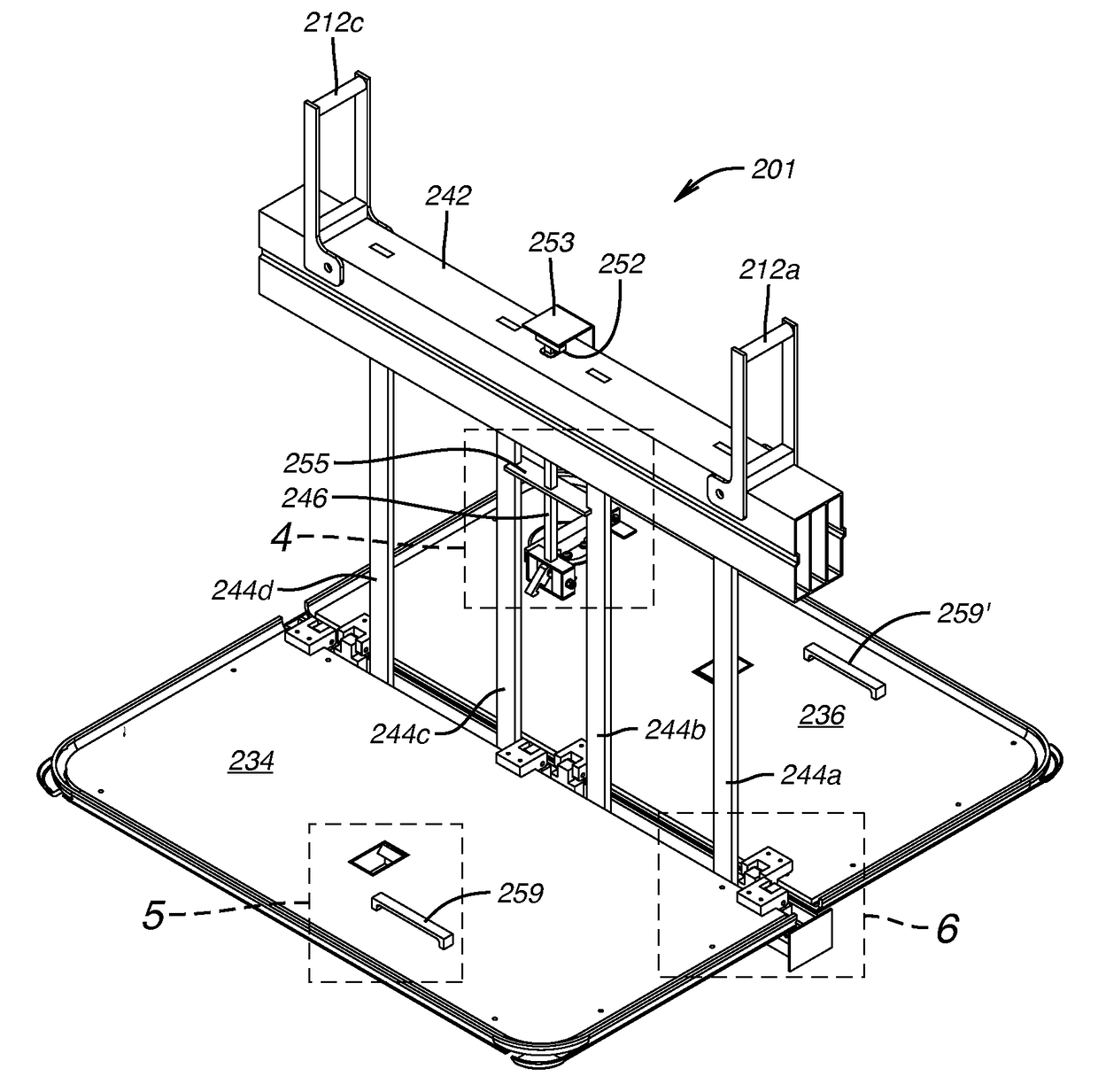
[0030]In accordance with this invention apparatus for installation in a ventilation shaft already fluidly communicating between an atmospheric opening and an underground ventilation duct allows the ventilation when there is no treat of flooding and on threat of flooding is manually operable to close ventilation from the atmospheric opening and prevent downward flow into the underground ventilation duct of surface water entering the atmospheric opening.

[0031]The concepts embodied in the exemplary embodiments of such apparatus described herein have application to any system in which an atmospheric opening communicates with a ventilation duct for an underground chamber or tunnel or other underground structure requiring ventilation, and through which opening substantial volumes of water can enter, whether by heavy rain or by storm surge propelled by hurricane or tropical storm or otherwise.

[0032]In the descriptions of exemplary embodiments of the invention that follow, reference is made...


PUM


Abstract

Apparatus allowing ventilation through a ventilation shaft to an underground ventilation duct fluidly communicating through the ventilation shaft to an atmospheric opening of the shaft and on threat of flooding operable to prevent downward flow of surface water into the ventilation duct includes support sidewalls fitting in the shaft providing a ventilation passage between support top and bottom openings and a suspension member supported on opposed lateral sidewalls proximate the top opening holding one or more hinge connected panels that manually release to rotationally close the passage and are manually rotationally liftable to a home position allowing ventilation. A releasable latching system between panel and a suspension member holder catches rising panels to hold them in home position ready for release.

Description

CROSS REFERENCE TO RELATED APPLICATION[0001]This application is a continuation-in-part of and claims the benefit of U.S. application Ser. No. 14 / 506,778 filed Oct. 6, 2014, which claimed the benefit of U.S. Provisional Application No. 61 / 887,416, filed Oct. 6, 2013, as does this application, and further claims the benefit of U.S. Provisional Application No. 62 / 363,024, filed Jul. 15, 2016, the disclosures of all of which are incorporated herein by reference.STATEMENT REGARDING FEDERALLY SPONSORED RESEARCH AND DEVELOPMENT[0002]Not applicableBACKGROUND OF THE DISCLOSURETechnical Field[0003]This invention relates to blocking flooding water from entering underground ventilation passages.Background Art[0004]Surface storm waters entering and flooding underground tunnels and chambers through ventilation ducts connecting the underground chambers or tunnels to air at ground surface affect without limitation, underground transportation tunnels for road vehicles, trains, and subways, and under...

Claims


Application Information

Patent Timeline
IPC IPC(8): F24F13/14E06B3/38E02D19/02E06B5/00E21F1/08F24F7/04
CPCF24F13/1413E21F1/08E02D19/02F24F2221/52E06B5/00F24F7/04E06B3/38E06B9/04E05F1/02E05Y2800/252E05Y2800/428E06B2009/007E05Y2400/3013E04H9/145
Inventor WATERS, JR., LOUIS A.EASTMAN, NICK ADAM
Owner FLOODBREAK
Why Eureka
Try Eureka