Smart Frame for Camera System

Inactive Publication Date: 2017-11-09
GOPRO
View PDF25 Cites 21 Cited by
  • Summary
  • Abstract
  • Description
  • Claims
  • Application Information

AI Technical Summary

Problems solved by technology

In such embodiments, it can be difficult to quickly access various camera interaction mechanisms (such as touch-screen displays) and to navigate camera interfaces (for instance, through multiple

Method used


Image

  • Smart Frame for Camera System
  • Smart Frame for Camera System
  • Smart Frame for Camera System

Examples


example camera

Frame and Camera System Configuration

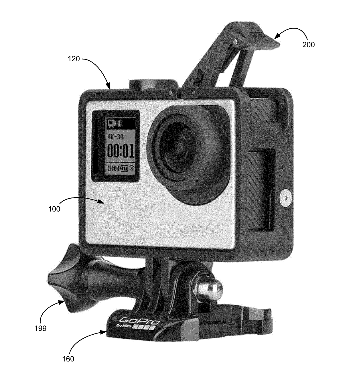
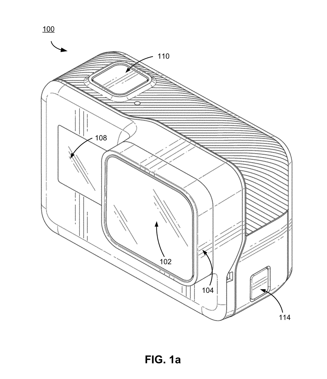
[0021]FIG. 1a illustrates a camera 100 for use with the camera systems described herein, according to one example embodiment. The camera 100 is configured to capture images and video, and to store captured images and video for subsequent display or playback. The camera 100 is adapted to fit within a camera housing, such as the camera frame described herein or any other suitable housing. As illustrated, the camera 100 includes a lens 102 configured to receive light incident upon the lens and to direct received light onto an image sensor internal to the lens. The lens 102 is enclosed by a lens ring 104.

[0022]The camera 100 can include various indicators, including the LED display 108 shown in FIG. 1a. The camera 100 can also include a shutter button 110 configured to allow a user of the camera to interact with the camera, to capture images and video, and to perform other camera functions. The camera 100 can also include one or more microphones (not...


PUM


Abstract

A camera smart frame is configured to enclose and communicatively couple to a camera. The camera smart frame includes one or more sets of input mechanisms, such as buttons. Each input mechanism can be programmed by a user to perform a selected camera function or configure a camera based on a selected camera configuration. A user can select, via a camera interface, a function or configuration, a smart frame input mechanism, and can associate the selected input mechanism and the selected function or configuration. When the smart frame is subsequently coupled to the camera, and a user interacts with the selected input mechanism, a camera controller identifies the function or configuration associated with the selected input mechanism and configures the camera accordingly.

Description

BACKGROUNDTechnical Field[0001]This disclosure relates to camera housings, and more specifically, to a smart camera frame that includes interface mechanisms for performing camera functions.Description of the Related Art[0002]Digital cameras are increasingly used in outdoors and sports environments. Often, these cameras are coupled to users, sports equipment, or vehicles. In such embodiments, it can be difficult to quickly access various camera interaction mechanisms (such as touch-screen displays) and to navigate camera interfaces (for instance, through multiple camera menus) to configure the camera in a desired mode. Further, cameras often minimize the number of certain camera interaction mechanisms (such as buttons) in order to streamline such interaction mechanisms. Accordingly, configuring a camera often requires a user to be able to view a display and to navigate multiple camera menus using very few interaction mechanisms. Satisfying such requirements may not be possible in hig...

Claims


Application Information

Patent Timeline
IPC IPC(8): H04N5/225H04N5/232
CPCH04N5/2252H04N5/23225H04N5/23203H04N5/2253H04N23/51H04N23/66H04N23/617
Inventor MOSKOVCHENKO, STEPAN
Owner GOPRO
Why Eureka
Try Eureka