Camera control system that controls a plurality of linked cameras

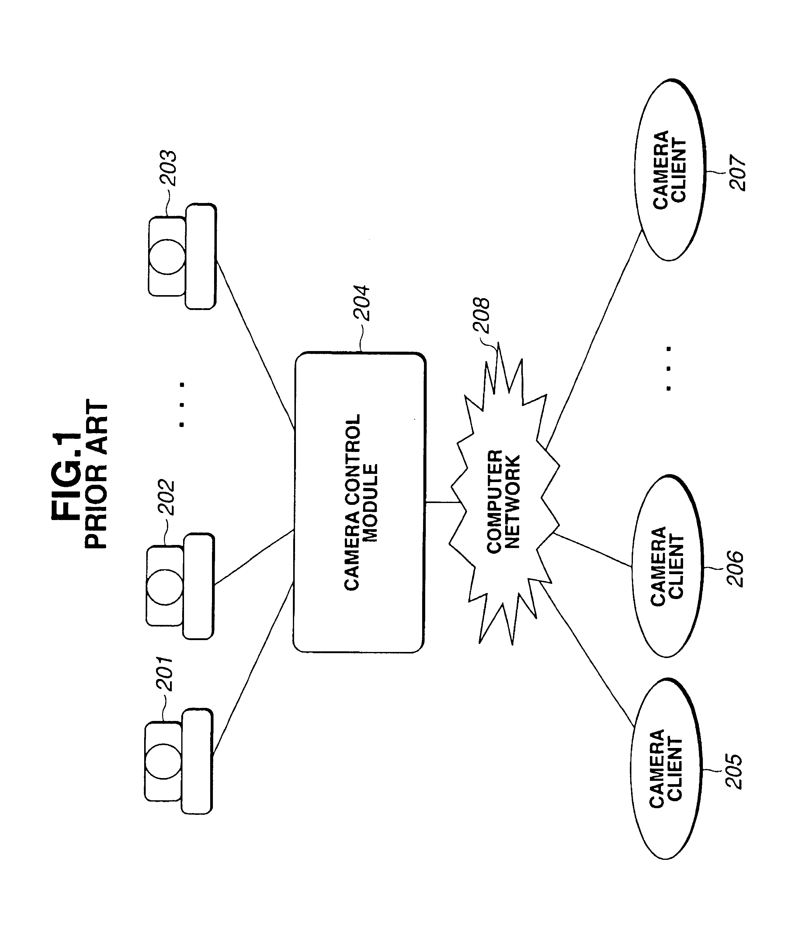
a camera control system and camera technology, applied in the field of camera control systems, can solve the problems of difficult to cause a plurality of cameras to operate in cooperation with one another, and cannot operate other cameras simultaneously

Inactive Publication Date: 2005-06-21
CANON KK
View PDF6 Cites 85 Cited by
  • Summary
  • Abstract
  • Description
  • Claims
  • Application Information

AI Technical Summary

Benefits of technology

[0015]It is an object of the present invention to provide a camera control system, a camera control method, a camera control server, a camera

Problems solved by technology

Even in such systems, however, only a single camera can be actually be operated, and it is impossible to operate other cameras simultaneously.
Accordingly, it is

Method used


Image

  • Camera control system that controls a plurality of linked cameras
  • Camera control system that controls a plurality of linked cameras
  • Camera control system that controls a plurality of linked cameras

Examples


first embodiment

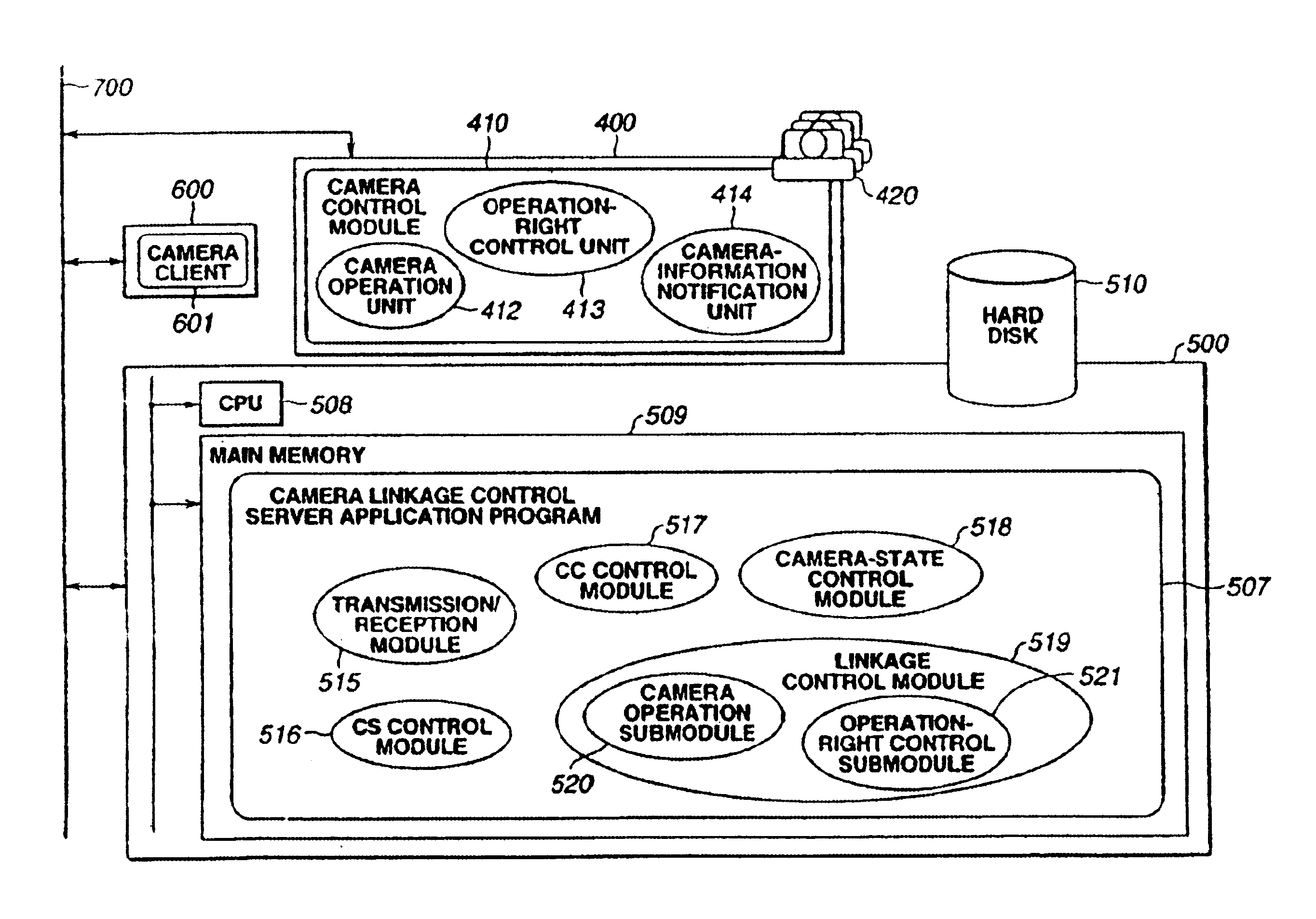
[0043]In a first embodiment of the present invention, the conventional remote camera system shown in FIG. 1 is improved, and software titled a “camera linkage control server” is introduced in addition to the camera control module.

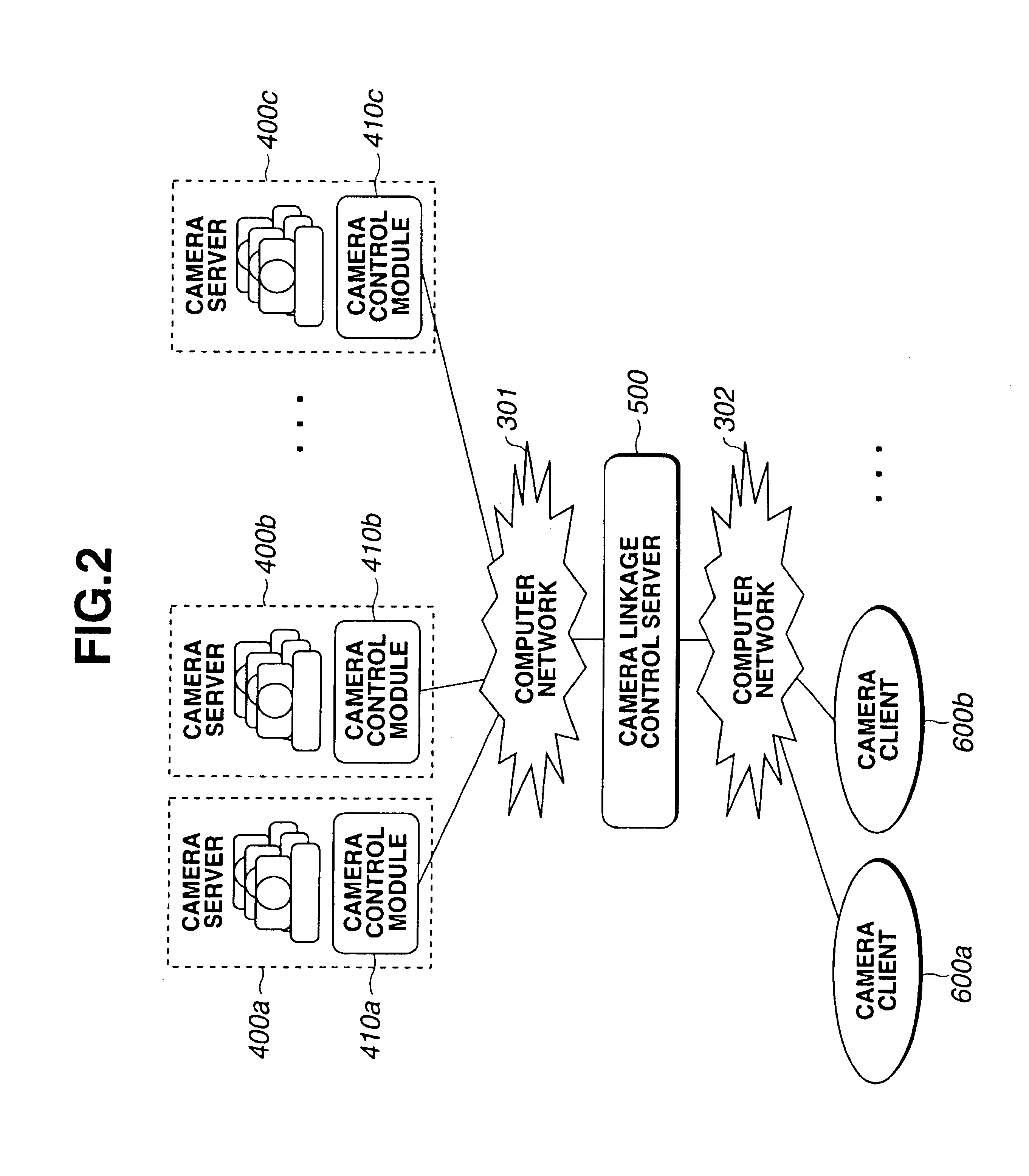
[0044]FIG. 2 is a block diagram illustrating an outline of the configuration of a remote camera system according to the first embodiment.

[0045]In FIG. 2, the remote camera system includes a plurality of camera servers 400a, 400b and 400c having corresponding camera control modules 410a, 410b and 410c, a plurality of camera clients 600a and 600b, a computer network 301 to which the camera control modules 410a, 410b and 410c are connected; a computer network 302 to which the camera clients 600a and 600b are connected, and a camera linkage control server 500 provided between the networks 301 and 302.

[0046]The camera client is a user who intents to utilize a remote camera via the networks. Actually, the user is, for example, a personal computer system, a work s...

second embodiment

[0199]A second embodiment of the present invention will now be described. FIG. 21 is a block diagram illustrating the concept of the second embodiment.

[0200]In the first embodiment, each unit for camera linkage is realized as independent software in the form of a multi-camera control server. In the second embodiment, however, each unit for camera linkage is incorporated in a camera control module. In addition, the camera control module itself is not operated by a PC which is independent of a camera, but operates in a CPU or a main memory incorporated in the camera.

[0201]Accordingly, as shown in FIG. 21, in the second embodiment, camera control modules 1401a, 1401b and 1401c are incorporated within cameras 1400a, 1400b and 1400c, respectively. It is assumed, however, that the camera control modules 1401a, 1401b and 1401c have the same function as the camera control module in the first embodiment. Each of the camera control modules 1401a, 1401b and 1401c performs communication with ca...


PUM


Abstract

In order to allow the user to access an arbitrary camera from an arbitrary camera client via a network, and to cause a plurality of cameras to perform a linked movement, a camera linkage server includes a communication path to each camera client, a client control module for controlling a camera used by the camera client, a communication path to each camera server, a camera server control module for controlling the camera used by the camera server, a camera server for controlling each of a plurality of cameras, a camera control module for controlling a camera client having an operation right for the camera and a state of the camera, and a linkage control module, having linked-movement defining information for defining a linked movement between each camera and other cameras, for recognizing a request for connection from an arbitrary camera client to an arbitrary camera via a corresponding client control module, and providing the other camera to perform a linked movement in accordance with the request for the connection with a request for connection via a corresponding camera server control module and a corresponding camera control module, based on the linked-operation defining information.

Description

BACKGROUND OF THE INVENTION[0001]1. Field of the Invention[0002]The present invention relates to a camera control system, a camera control method, a camera control server, a camera apparatus, a user interface apparatus, and the like for distributing an image via a computer network, such as the Internet, an Intranet or the like. More particularly, the invention relates to an improvement in a operation of a video camera installed at a remote location in image distribution service.[0003]2. Description of the Related Art[0004]Recently, in accordance with the spread of computer networks, such as the Internet, Intranets and the like, “remote apparatus service systems” which allow the user to operate a peripheral apparatus, such as a printer, a scanner or the like, installed at a remote location via a computer network have been produced more and more.[0005]A “remote camera system” is one such system. In a remote camera system, an image from a video camera installed at a remote location can...

Claims


Application Information

Patent Timeline
IPC IPC(8): G06F13/00G06T1/00H04N7/18H04N5/232
CPCH04N7/181
Inventor FUKASAWA, TOSHIHIKO
Owner CANON KK
Why Eureka
Try Eureka