Supercharge Your Innovation With Domain-Expert AI Agents!

Retractable wheel assembly

a technology of retractable wheels and arm assemblies, which is applied in the direction of trailers, suspensions, and resilient suspensions, can solve the problems of high cost of manufacturing and design of light weight high strength materials, and considerably increase the overall design cost of utility applications, so as to avoid vibration of the arm assemblies during operation

Active Publication Date: 2017-11-16
SIERRA LUIS
View PDF0 Cites 12 Cited by
  • Summary
  • Abstract
  • Description
  • Claims
  • Application Information

AI Technical Summary

Benefits of technology

This patent describes a retractable wheel assembly for an aircraft that prevents accidental folding of the arm assemblies connected to the wheels during landing. The assembly includes a guide way defined by a pair of guide blocks centrally positioned between the arm assemblies, and the threaded shaft is configured to traverse in the forward and the backward movement through the guide way. The wheels are hingedly connected to the lower frame of the aircraft via a high strength arm frontally positioned to each wheel and a shock absorber arm rearwardly positioned to the wheels, to avoid vibrations of the arm assemblies during operation. The wheels are also configured to be extended across a predefined span via radially extending the arm assembly, which stabilizes the landing of the aircraft.

Problems solved by technology

Most of the retractable wheel systems used nowadays employ a complex design which uses high strength materials in high quantities, which considerably increase the cost of the overall design of the utility applications.
Even aircrafts which use retractable landing gears make use of light weight high strength materials which are expensive to manufacture and design.

Method used


Image

  • Retractable wheel assembly
  • Retractable wheel assembly
  • Retractable wheel assembly

Examples


Embodiment Construction

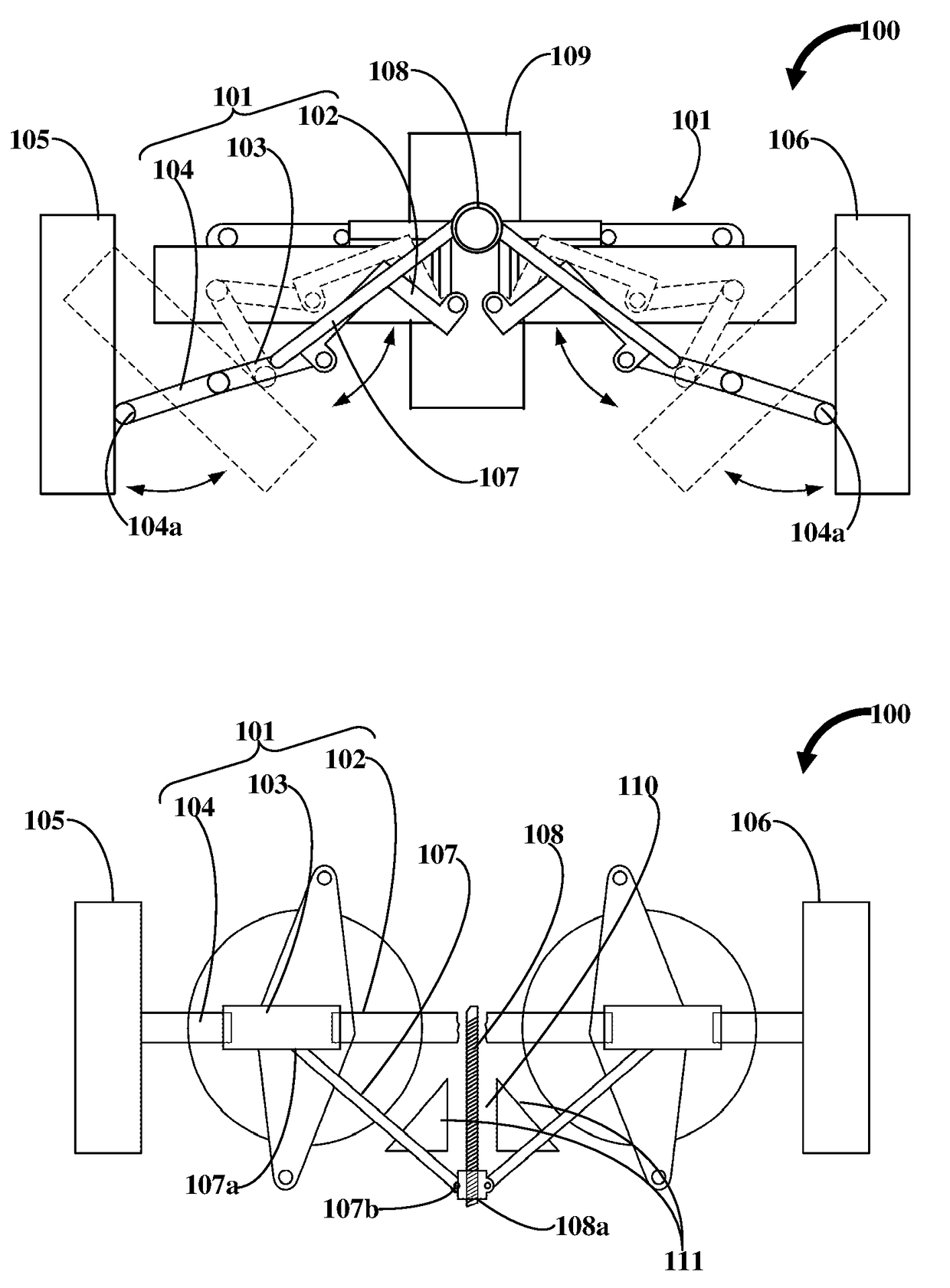
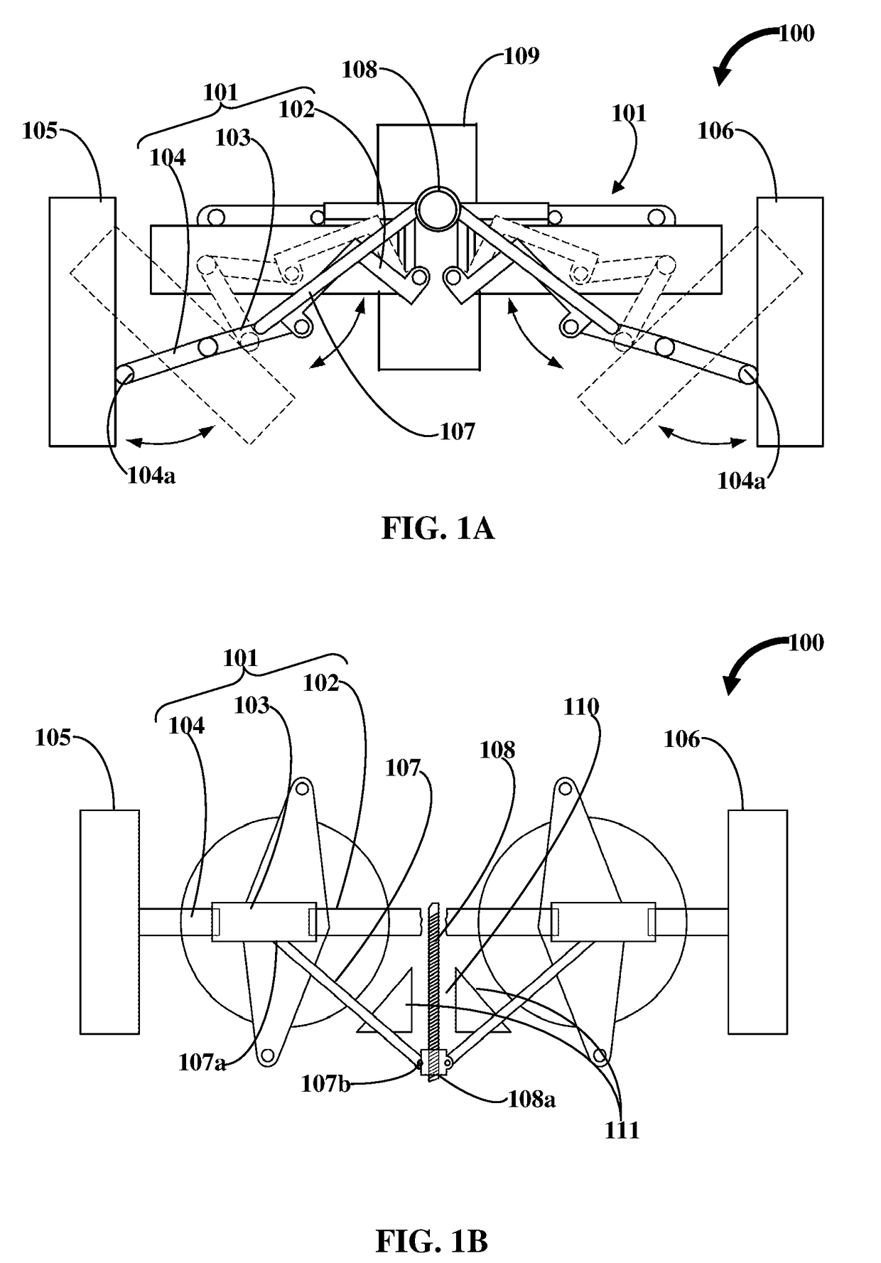
[0013]With reference to FIGS. 1A-1B, the retractable wheel assembly 100 disclosed herein comprises at least two arm assemblies 101, a pair of wheels 105 and 106, a retraction arm 107, and the threaded shaft 108. The arm assemblies 101 are hingedly attached to a lower frame 109 of a utility vehicle, and symmetrically disposed along the lower frame 109. Each arm assembly 101 comprises a first arm 102 hingedly connected to the lower frame 109, a second arm 103 hingedly linked to the first arm 102, and a third arm 104 hingedly linked to the second arm 103. Each wheel is hingedly connected at distal ends 104a, as shown in FIG. 1A, of the third arm 104 of each arm assembly 101, and hingedly connected to the lower frame 109. One end 107a of the retraction arm 107 is hingedly connected to the second arm 103, and a distal end 107b of the retraction arm 107 in hinged connection with an end 108a of a threaded shaft 108. Here, the threaded shaft 108 is centrally positioned between the two arm a...


PUM


Abstract

A retractable wheel assembly includes arm assemblies, wheels, a retraction arm, and a threaded shaft. The arm assemblies are hingedly attached to a lower frame of a utility vehicle. Each arm assembly comprises a first arm, a second arm, and a third arm hingedly linked there between. Each wheel is connected to the third arm of each arm assembly. The retraction arm is connected to the second arm, and a threaded shaft. The threaded shaft is configured to be actuated rearwardly where the retraction arm is rearwardly pulled causing the second arm to unfold the arm assembly outwardly and deploy the wheels and for motion of the utility vehicle. Then, the threaded shaft is configured to be actuated forwardly where the retraction arm is pushed forward causing the second arm to fold the arm assembly inwardly and fold the wheels and when the utility vehicle is positioned at rest.

Description

BACKGROUND[0001]Most modern day vehicles have conventional wheel assemblies that has not undergone any substantial changes in design. In general, according to conventional mechanical practices, the wheels are attached at opposing ends of a drive shaft, suspended by a strut assembly, and separated by, for example, a sway bar. This is the general construction of vehicles. But in the case of selective application of wheels, where wheels were used only when needed, retractable wheel systems were introduced. The best example of such retractable wheels is in aircraft design which requires retractable wheel system for takeoff and landing. The retractable wheel system also finds further application in utility trailers which are used for a dual purpose of containment of load, as well as transport of the load. The transport of the utility trailers require wheels that can be retracted from a slot beneath the chassis of the utility trailers.[0002]Most of the retractable wheel systems used nowad...

Claims


Application Information

Patent Timeline
Patent Type & Authority Applications(United States)
IPC IPC(8): B64C25/20B62D63/06B64C25/12
CPCB64C25/20B62D63/061B62D63/062B64C25/12B60G3/20B60G2204/47B60G2300/04
Inventor SIERRA, LUIS
Owner SIERRA LUIS
Features
  • R&D
  • Intellectual Property
  • Life Sciences
  • Materials
  • Tech Scout
  • Unparalleled Data Quality
  • Higher Quality Content
  • 60% Fewer Hallucinations
Learn More