Flexion and extension range limiting hinge for an orthopedic brace
a technology of limiting hinges and flexion and extension range, applied in the field of anatomical support braces, can solve problems such as the user may require multiple limitations angles
- Summary
- Abstract
- Description
- Claims
- Application Information
AI Technical Summary
Benefits of technology
Problems solved by technology
Method used
Image
Examples
first embodiment
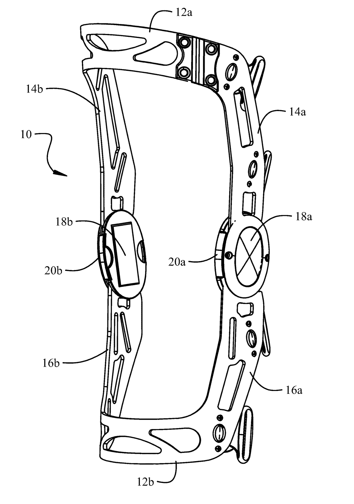
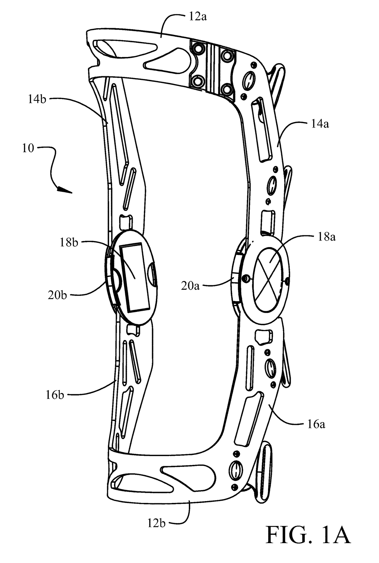
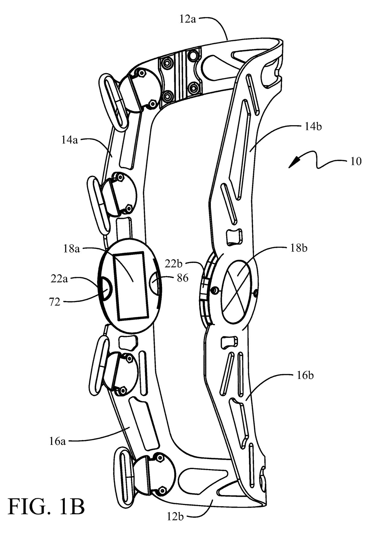
[0029]Details of a first embodiment for the angle limit elements and the associated engagement mechanisms for retention in the ports are shown in FIG. 2D. The extension angle limit element 60 has a body 64 which includes limiting surfaces 66 which are adapted to be engaged by mating faces 68 indented in anterior edges of the struts 14, 16. The surface tab 20 of the extension angle limit element 60 is received in an anterior recess 70 in the hinge plate 24 when the body of the extension angle limit element is received in the anterior port between the hinge plate and hinge assembly cap 26 (as described with respect to FIG. 2A). Engagement of the surface tab 20 in the recess 70 limits the insertion depth of the extension angle limit element into the port. A raised stop 71 also engages the body to limit insertion depth. A bottom relief 72 (also seen in FIG. 1B) in the recess 70 allows a lower edge of the surface tab 20 to be grasped with a fingernail to assist in removal of the extensio...
second embodiment
[0032]A second embodiment is shown in FIGS. 3A and 3B with the hinge assembly cap removed wherein the extension and flexion angle limit elements 62 and 64 are constrained in the ports in the hinge assembly with cylindrical buttons 100 and 102 received in cylindrical cutouts 104 and 106 in the bodies 64 and 78 respectively. Channels 108 and 110 cut into the bodies 64 and 78 transecting the cylindrical cutouts 104 and 106. Buttons 100 and 102 are depressible into the hinge plate 26 by engaging extending tabs 112 and 114 with the pen 92 or similar tool extending through apertures 94 in the hinge assembly cap (as described with respect to FIG. 2E). The transecting channels 108 and 110 are sized for clearance with the tabs 112 and 114 to allow insertion or extraction of the angle limit elements from the hinge assembly ports when the buttons are depressed.
third embodiment
[0033]A third embodiment is shown in FIGS. 4A and 4B with the hinge assembly cap 26 rotated 90° to show features on the lower surface. The bodies 64 and 78 of the extension and flexion angle limit elements 60 and 62 are substantially bifurcated with capped slots 116 and 118 to form flexible jaw pairs 120a, 120b and 122a, 122b. The capped slots have transverse reliefs 124 and 126 and substantially cylindrical indentations 128 and 130. The cylindrical indentations of the jaws resiliently receive restraining posts 132 and 134 which depend from a lower surface of the hinge assembly cap 26 (or in alternative embodiments extend from an upper surface of the hinge plate 24) to extend between the hinge plate and hinge assembly cap. The jaw pairs are sufficiently flexible to allow insertion and extraction of the angle limit elements from the ports in the hinge assembly. However, key holes 136 and 138 may be present proximate the transverse reliefs to allow insertion of the pen 92 through aper...
PUM
 Abstract
Description
Claims
Application Information
 - R&D
- Intellectual Property
- Life Sciences
- Materials
- Tech Scout
- Unparalleled Data Quality
- Higher Quality Content
- 60% Fewer Hallucinations
Browse by: Latest US Patents, China's latest patents, Technical Efficacy Thesaurus, Application Domain, Technology Topic, Popular Technical Reports.
© 2025 PatSnap. All rights reserved.Legal|Privacy policy|Modern Slavery Act Transparency Statement|Sitemap|About US| Contact US: help@patsnap.com


