Double sided measuring tape

Inactive Publication Date: 2017-11-30
DRURY SR DENNIS E
View PDF13 Cites 0 Cited by
  • Summary
  • Abstract
  • Description
  • Claims
  • Application Information

AI Technical Summary

Benefits of technology

[0012]The present invention provides a substantial improvement over those inventions found in the prior art. For example, the design of the present invention permits the user to quickly and easily measure both external measurements and internal measurements and read the corresponding distance directly off of the measuring t

Problems solved by technology

It is known that there is difficulty

Method used


Image

  • Double sided measuring tape
  • Double sided measuring tape
  • Double sided measuring tape

Examples


Example

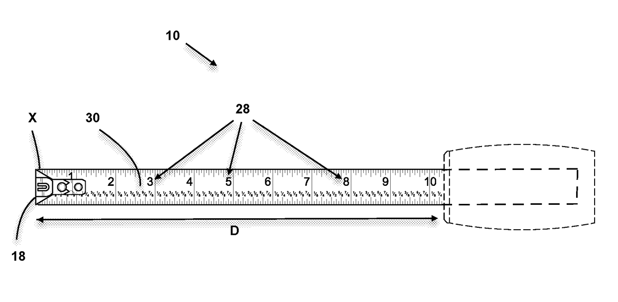
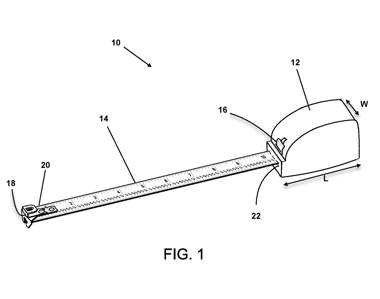
[0020]Referring now to the drawings, the double sided measuring tape of the present invention is generally designated by the numeral 10. The double sided measuring tape includes a rigid plastic or metal housing 12 which encloses a generally semi-flexible metal or plastic measuring tape 14 and a locking mechanism 16. The housing 12, measuring tape 14, lock mechanism 16, and components thereof which enable the extension and retraction of measuring tape 14 from housing 12 function in a similar manner as those measuring tapes found in the prior art and therefore further discussion of the specific details of the operation of the extension, retraction, and locking elements of the measuring tape 14 of the double sided measuring tape 10 of the present invention will are understood to those skilled in the art. There are numerous modifications, variations and derivations as to the locking mechanisms of measuring tapes in the prior art which are within the scope of the instant invention.

[0021]...


PUM


Abstract

A linear measuring device includes a tape housing and a semi-flexible measuring tape housed within the tape housing of a length L in a generally spiral configuration with an outer end extendable through a tape outlet opening and having a flange thereon. The tape having two sets of measurements, a first set displayed on a top side of the measuring tape with a first incremental measurement X, and second set displayed on a bottom side of the measuring tape with a first incremental measurement X+L.

Description

[0001]This is a continuation-in-part which claims the benefit of an earlier filed U.S. application Ser. No. 29 / 565688 filed May 24, 2016.BACKGROUND OF THE INVENTION1. Field of Invention[0002]The present invention relates to tape measure devices and, more particularly, to a tape measure which includes a housing in which a flexible measuring tape having two distinct sets of measurement numbers or instantly providing internal or external measurements, depending on the measurement reading desired.2. Description of the Prior Art[0003]There are various types of measuring tapes. In many cases, internal measurements of openings, spaces, and objects must be made, and these measurements must be accurate to ensure that the proper fitting of materials is permitted. This is common in between drywall and replacement window industry involves the replacement insertion of cabinets or window replacement. In order to properly seat the item within the opening, extremely accurate measurements must be ma...

Claims


Application Information

Patent Timeline
IPC IPC(8): G01B3/10
CPCG01B3/1082G01B2003/103G01B3/1041G01B3/1003
Inventor DRURY, SR., DENNIS E.
Owner DRURY SR DENNIS E
Why Eureka
Try Eureka