Power transmission shaft

a technology of transmission shaft and circlip, which is applied in the direction of yielding coupling, coupling, fastening means, etc., can solve the problems that the visual recognition of the engagement stop state of the circlip (retaining ring) cannot be externally recognized, and the appropriate attachment of the propeller shaft (the power transmission shaft) cannot be carried out. , to achieve the effect of preventing the drop-out of the circlip, improving the workability of the linkage, and preventing the drop-ou

Active Publication Date: 2018-01-04
HITACHI ASTEMO LTD
View PDF16 Cites 12 Cited by
  • Summary
  • Abstract
  • Description
  • Claims
  • Application Information

AI Technical Summary

Benefits of technology

[0006]According to the present invention, a drop out of the vehicle side rotational shafts is prevented in a form of a fitting of the circlip (retaining ring) onto the cylindrical section so that an engagement stop state of the vehicle side rotational shafts with the circlip (retaining ring) can be recognized from an external. Consequently, an appropriate prevention of the drop-out of the circlip can be secured.
[0007]In addition, according to the present invention, the circlip (retaining ring) can also engageably be stopped into the engagement stop groove by an insertion of the vehicle side rotational shafts in the state in which the circlip (retaining ring) is previously fitted into the cylindrical section. The engagement stop operation according to the circlip (retaining ring) can become easier and an improvement of a linkage workability (operability) between the propeller shaft (power transmission shaft) and the vehicle side rotational shafts can be achieved.

Problems solved by technology

However, since, in the previously proposed propeller shaft, the circlip (retaining ring) is engageably stopped into the engagement stop groove located at the inner peripheral side of each constant velocity (universal) joint (an inner wheel member), a visual recognition of the engagement stop state of the circlip (retaining ring) cannot externally be recognized.
Thus, there is a possibility that an appropriate attachment of the propeller shaft (the power transmission shaft) cannot be carried out.

Method used


Image

  • Power transmission shaft
  • Power transmission shaft
  • Power transmission shaft

Examples


first embodiment

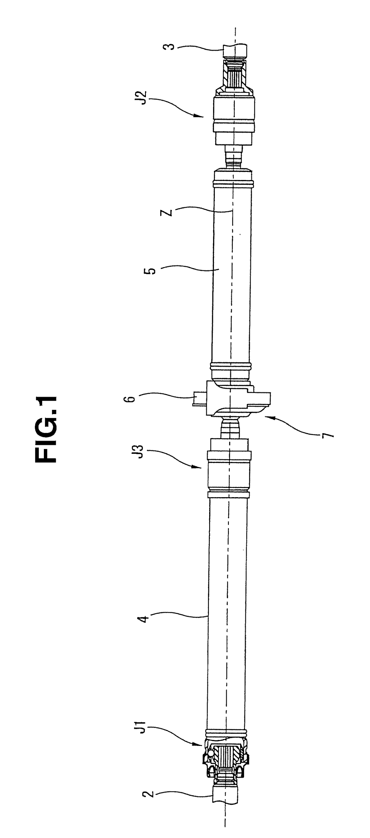
[0028]FIGS. 1 through 13(b) show a first preferred embodiment of the power transmission shaft (also called the propeller shaft) according to the present invention. FIG. 1 shows a side view of the power transmission shaft (propeller shaft) representing a whole of the propeller shaft (power transmission shaft).

[0029]It should be noted that, in the following description, for convenient purposes, a left side of FIG. 1 is explained as a front, a right side of FIG. 1 is explained as a rear, a direction along a rotation center axial line in FIG. 1 is explained as an axial (shaft) line, and a direction around a rotational center axial (shaft) line is explained as a peripheral direction.

[0030](Structure of Power Transmission Shaft)

[0031]Power transmission shaft 1 includes: a driving shaft 4 integrally rotatably linked to an input shaft 2 interlinked to a transmission (not shown) via a first constant velocity (universal) joint J1; and a driven shaft 5 integrally rotatably linked to an output ...

second embodiment

[0096]FIG. 15 shows a second preferred embodiment of the propeller shaft (power transmission shaft) according to the present invention. In the second embodiment, the shape of circlip (retaining ring) 8 in the case of the first embodiment is modified. It should be noted that the basic structure of the second embodiment is the same as the first embodiment except the modification of circlip (retaining ring) 8. Hence, for the same structure as the first embodiment, the same reference numerals are provided and their explanations will be omitted (the same as those described below).

[0097]That is to say, circlip (retaining ring) 81 in this embodiment is structured in such a way that first and second projection sections 41a, 42a are formed as projection sections in which portions of respective insertion sections 41, 42 are projected in the outsides of the radial directions on first and second insertion sections 41, 42 which are formed linearly in the first embodiment.

[0098]In other words, ci...

third embodiment

[0100]FIG. 16 shows a third preferred embodiment of the propeller shaft (power transmission shaft) according to the present invention.

[0101]In this embodiment, the shape of circlip (retaining ring) 8 described in the first embodiment is modified.

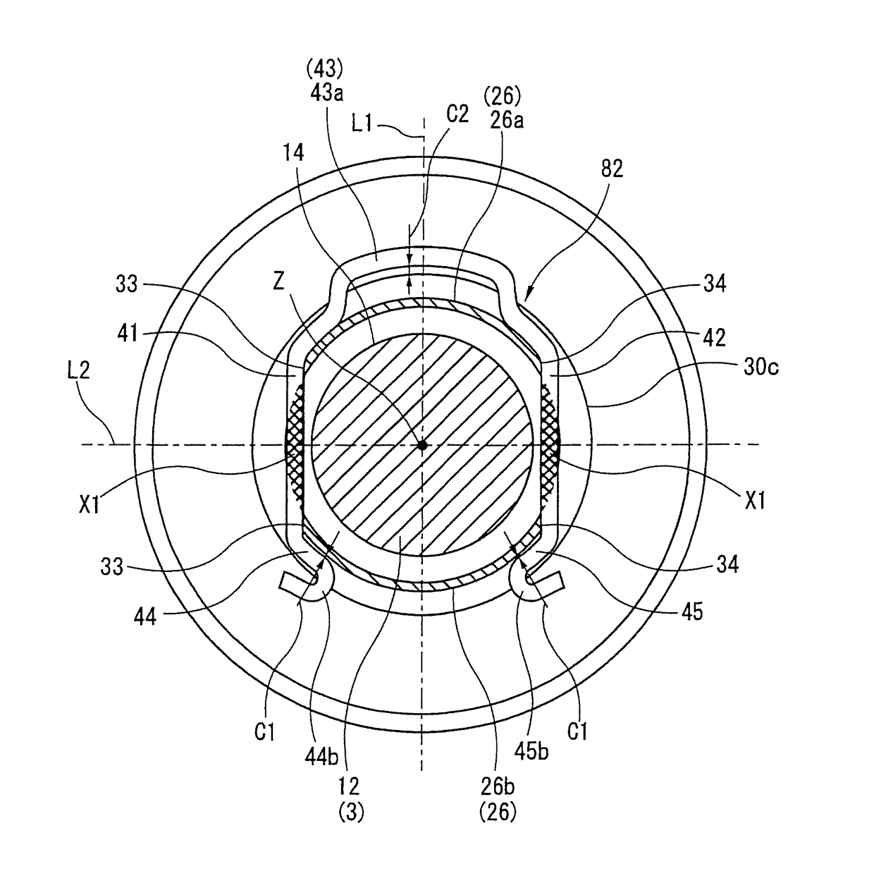
[0102]Circlip (retaining ring) 82 in this embodiment includes a projection section 43a formed in such a way that a portion of connection section 43 is offset toward a more radially outer side of cylindrical section 30 than an outer peripheral surface 30c of cylindrical section 30. In addition, a predetermined gap C2 is formed radially between projection section 43a and cylindrical section 30 in an appropriate mounting state of circlip (retaining ring) 82.

[0103]In addition, in circlip (retaining ring) 82 in this embodiment, first and second engagement sections 44, 45 are bent in folded shapes toward the outside (radially outside). At the same time, portions of bending sections which are brought in contact with cylindrical section 30 (retainin...


PUM


Abstract

A power transmission shaft is interposed between a first shaft section and a second shaft section. The power transmission shaft comprises: a cylindrical section rotated integrally with a shaft section and formed cylindrically; a through hole disposed in the cylindrical section and penetrated radially with respect to a rotational axial line, each of a pair of vehicle side rotational shaft sections having an engagement groove disposed on an outer peripheral side of the pair of vehicle side rotational shaft sections and extended in a direction around the rotational axial line and the engagement groove being exposed from the through hole; and a retaining ring (circlip) disposed to enclose at least a portion of the outer peripheral side of the cylindrical section, a portion of the retaining ring being inserted into the through hole from the outer peripheral side of the cylindrical section and being engaged with the engagement groove.

Description

BACKGROUND OF THE INVENTION(1) Field of the Invention[0001]The present invention relates to a power transmission shaft such as a propeller shaft applicable to, for example, an automotive vehicle for transmitting a driving force of a driving source to driving wheels of the vehicle.(2) Description of Related Art[0002]For example, a Japanese Patent Application Laid Open Publication No. 2013-194895 published on Sep. 30, 2013 discloses a previously proposed propeller shaft.[0003]That is, the previously proposed propeller shaft has an axial direction one end side via a constant velocity (universal) joint linked to a first shaft at a driving source side and axial direction other end side linked to a driving wheel side via another constant velocity (universal) joint. Then, at this time, the first shaft and the second shaft are linked to the respective constant velocity (universal) joints by an engagement stop of a circlip (retaining ring) fitted onto an outer peripheral side of the first an...

Claims


Application Information

Patent Timeline
Patent Type & Authority Applications(United States)
IPC IPC(8): F16D1/08B25B27/20F16B21/18F16D1/116F16D1/10F16D3/223
CPCF16D1/0894F16D1/116F16B21/186F16D2001/103F16D2003/22326F16D2003/22323F16D3/223B25B27/205
Inventor SUGIYAMA, KENICHIZHU, XIAOJINMABE, YASUTOMO
Owner HITACHI ASTEMO LTD
Why Eureka
Try Eureka