Spring assist cable clamps

a technology of spring assist and cable clamps, which is applied in the field of clamps, can solve the problems of not being suitable for bolted cable clamps and the need for mid-span drop connections

Active Publication Date: 2018-02-01
HUBBELL INC
View PDF0 Cites 15 Cited by
  • Summary
  • Abstract
  • Description
  • Claims
  • Application Information

AI Technical Summary

Problems solved by technology

However, there are instances where mid-span drop connections are needed.
However, such bolted c

Method used


Image

  • Spring assist cable clamps
  • Spring assist cable clamps
  • Spring assist cable clamps

Examples


Embodiment Construction

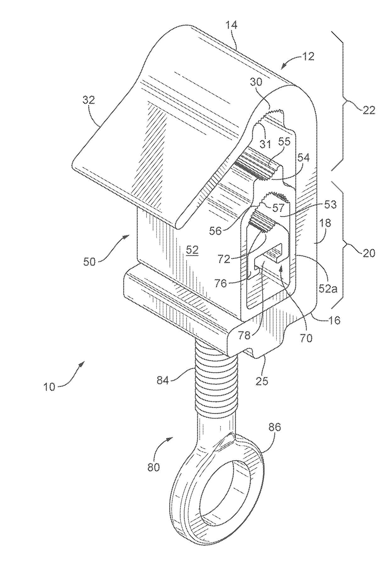
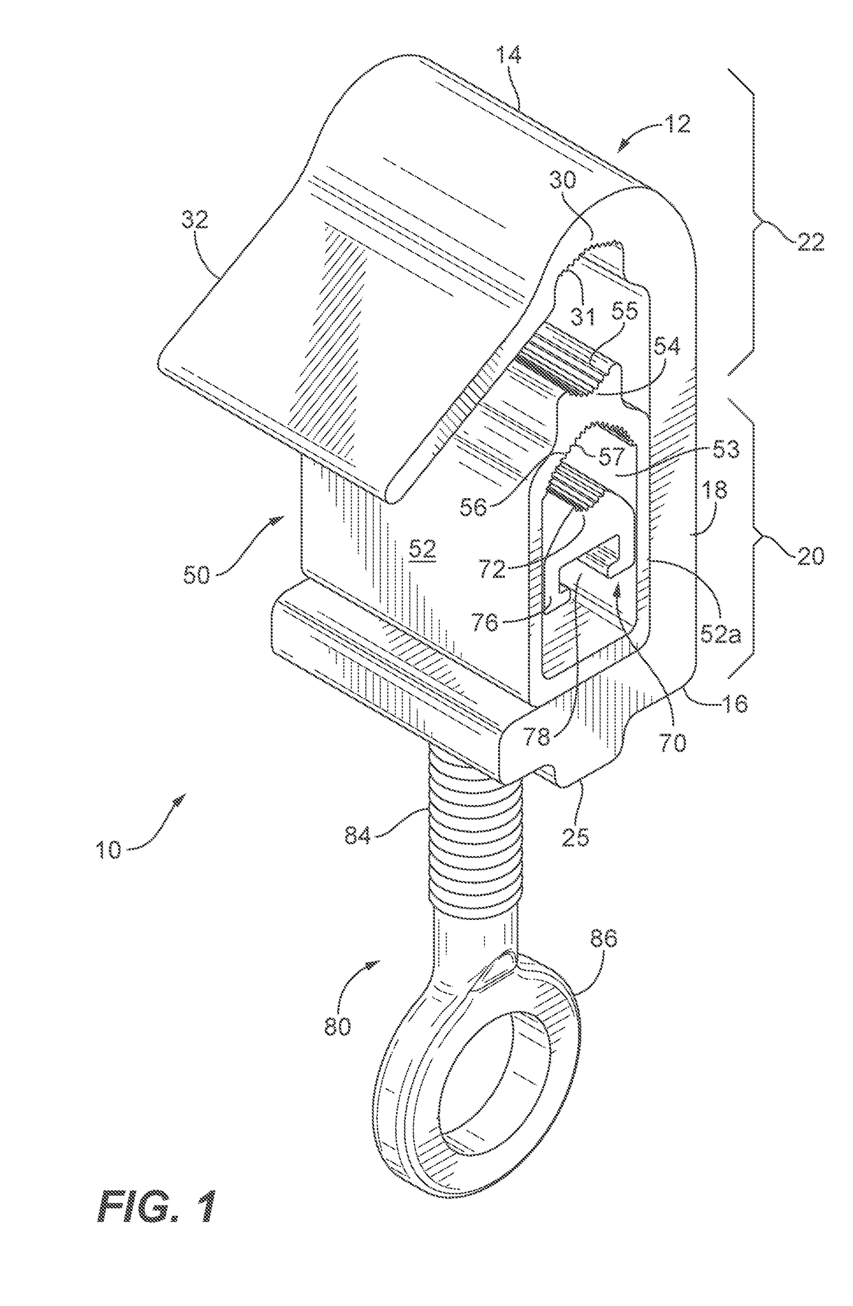
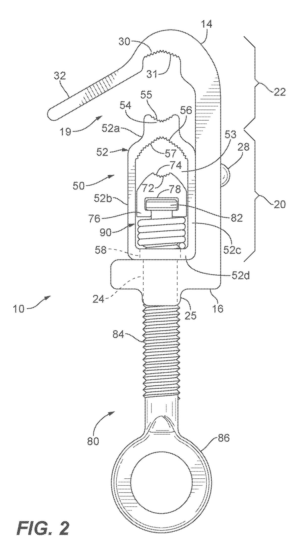
[0033]Exemplary embodiments of the cable clamp of the present disclosure are shown and described. For ease of description, the cable clamp described herein may also be referenced as the “clamp.” The clamp according to the present disclosure is configured to be installed from the ground with an extendable reach tool, such as for example a hot stick. Initial spring tension temporarily holds a tap conductor or drop cable in a drop cable section of the clamp, and a main span conductor or cable can be guided into a main span section of the clamp and tightened. For the purposes of the present disclosure, the tap conductor and drop cable are referred to as a drop cable. For the purposes of the present disclosure, a main span conductor and main span cable are referred to as a main span cable.

[0034]Referring now to the figures, in particular FIGS. 1-8, an exemplary embodiment of the clamp according to the present disclosure is shown. The clamp 10 includes a clamp body 12, a spacer 50, a keep...


PUM


Abstract

Cable clamps configured to be installed from the ground with an extendable reach tool, such as a hot stick, are provided. Initial spring tension temporarily holds a drop cable in a drop cable section of the clamp, and a main span cable can be guided into a main span section of the clamp and tightened.

Description

CROSS REFERENCE TO RELATED APPLICATIONS[0001]The present application is based on and claims benefit from co-pending U.S. Provisional Application Ser. No. 62 / 368,450 filed Jul. 29, 2016 entitled “Spring Assist Cable Clamps” the entire contents of which are incorporated herein by reference.BACKGROUNDField[0002]The present disclosure relates generally to clamps for utility cabling and more particularly to cable clamps for clamping drop cables to main span cables, or tap conductors to main span conductors.Description of the Related Art[0003]Aerial cabling, such as high tension electrical power conductors or fiber optic cabling for communications, data or media transmission is typically strung from utility pole to utility pole, or from a utility pole to a building. The electrical power conductor or fiber optic cabling between utility poles is often referred to as a main span conductor or cable.[0004]With aerial electrical power conductors, when power is to be supplied to an auxiliary sou...

Claims


Application Information

Patent Timeline
IPC IPC(8): G02B6/44G02B6/38
CPCG02B6/4471G02B6/3887G02B6/4429G02B6/483H02G1/04H02G7/08H02G3/32G02B6/48G02B6/50
Inventor SAKMAR, JOHN EDWARD
Owner HUBBELL INC
Why Eureka
Try Eureka