
Liquid crystal display panel and driving method thereof
- Summary
- Abstract
- Description
- Claims
- Application Information
AI Technical Summary
Benefits of technology
Problems solved by technology
Method used
Image

Examples
Embodiment Construction
[0047]To further expound the technical solution adopted in the present invention and the advantages thereof, a detailed description is given to a preferred embodiment of the present invention with reference to the attached drawings.
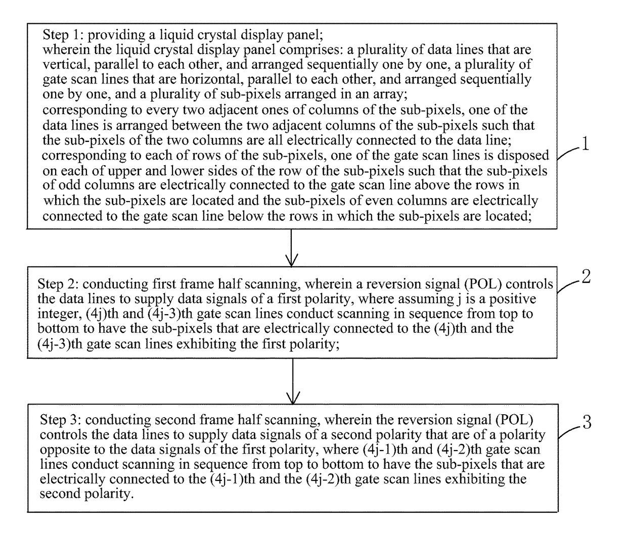
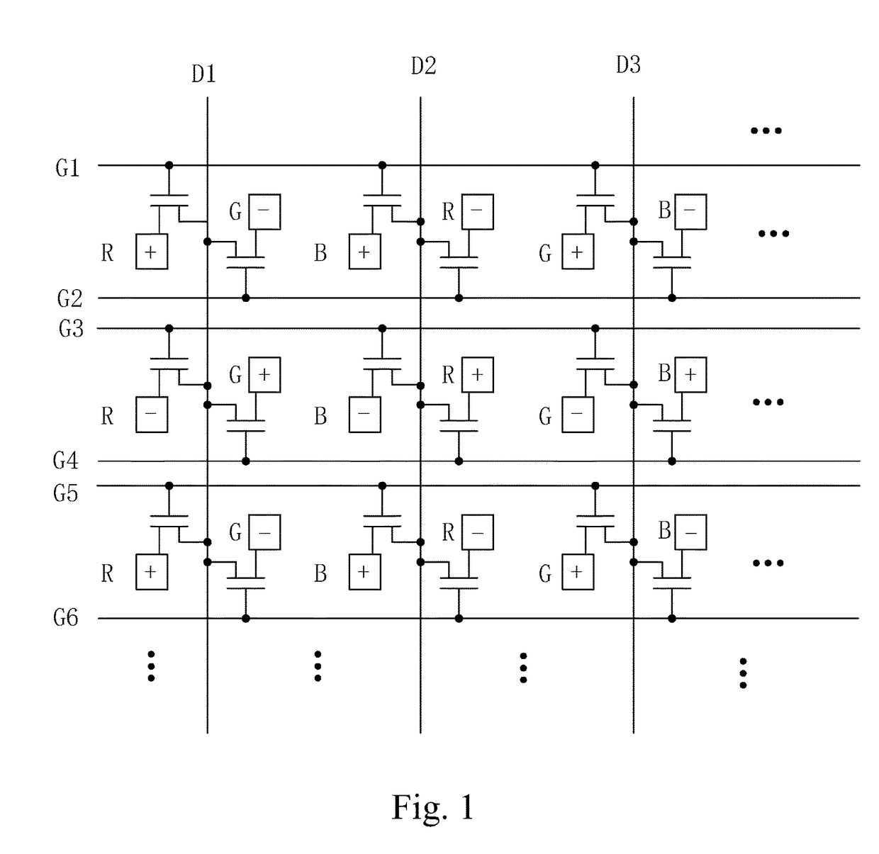
[0048]Referring collectively to FIGS. 3 and 4, firstly, the present invention provides a liquid crystal display panel, which comprises: a plurality of data lines (such as D1, D2, D3 and so on) that are vertical, parallel to each other, and arranged sequentially one by one, a plurality of gate scan lines (such as G1, G2, G3, G4, G5, G6, and son on) that are horizontal, parallel to each other, and arranged sequentially one by one, and a plurality of sub-pixels arranged in an array.
[0049]Specifically, as shown in FIG. 3, the sub-pixels comprise red sub-pixels R, green sub-pixels G, and blue sub-pixels B that are arranged, repeatedly and cyclically, in a horizontal direction from left to right and a display pixel 10 is formed of one red sub-pixel R, one green...
PUM
 Abstract
Description
Claims
Application Information