System and method for operating deactivated cylinders

Active Publication Date: 2018-03-01
FORD GLOBAL TECH LLC
View PDF1 Cites 1 Cited by
  • Summary
  • Abstract
  • Description
  • Claims
  • Application Information

AI Technical Summary

Benefits of technology

The patent describes a method for improving engine efficiency by using a deactivated cylinder. This is achieved by adjusting the timing of vacuum valves to increase engine pressure and improve fuel efficiency. The method also allows for higher recirculation flow rates during conditions of high intake manifold pressure, increasing engine power output. Overall, this approach allows for improved engine performance during operation with deactivated cylinders.

Problems solved by technology

The deactivated cylinders may hold fresh air or exhaust to reduce vacuum within the cylinders, but engine power may be lost by compressing and expanding the air.
The compression and expansion of the air provides minimal useful work.
Additionally, the approach may provide vacuum when vacuum production may be difficult.

Method used


Image

  • System and method for operating deactivated cylinders
  • System and method for operating deactivated cylinders
  • System and method for operating deactivated cylinders

Examples


Embodiment Construction

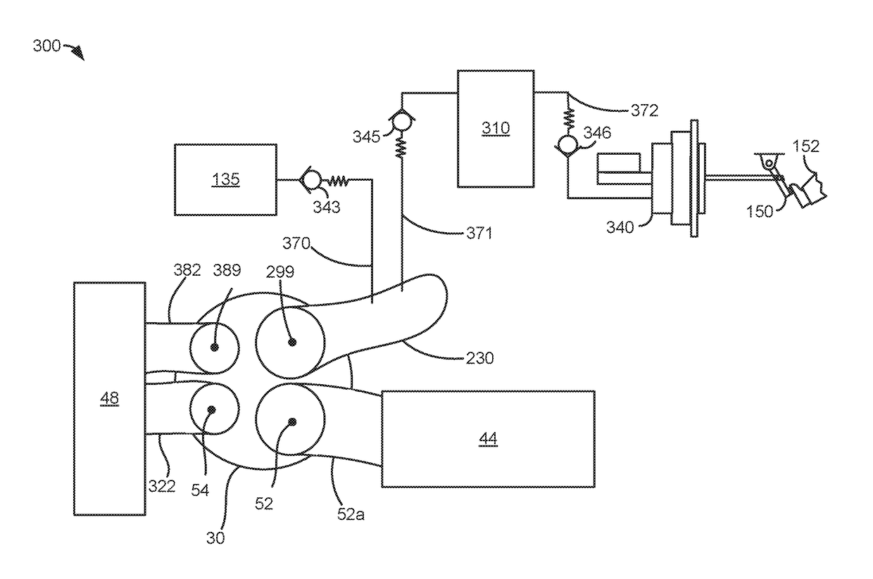
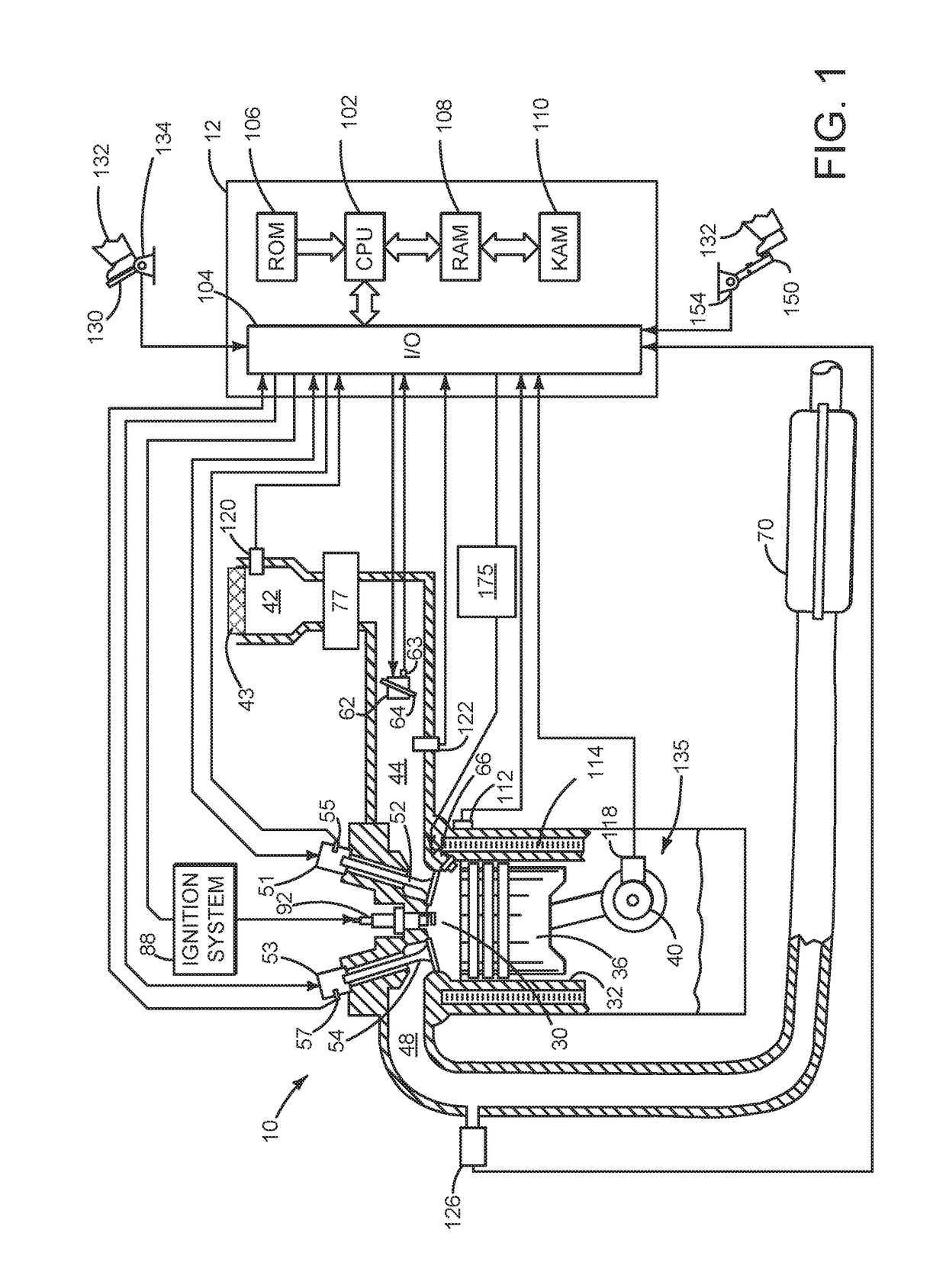
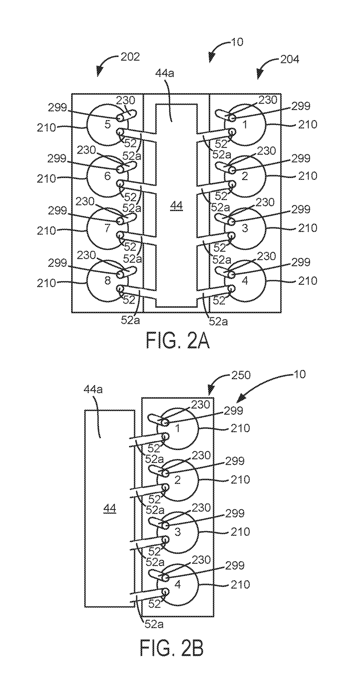
[0015]The present description is related to operating an engine with one or more cylinders that may be deactivated from time to time. The engine may be a boosted engine as shown in FIG. 1 or a naturally aspirated engine. The engine may include one or two cylinder banks as shown in FIGS. 2A and 2B. Cylinders of the engine may be supplied air via passages as shown in FIG. 3. One or more engine cylinders may operate as shown in the operating sequence of FIG. 4. The engine cylinders may be operated according to the method of FIG. 5.

[0016]Referring to FIG. 1, internal combustion engine 10, comprising a plurality of cylinders, one cylinder of which is shown in FIG. 1, is controlled by electronic engine controller 12. Engine 10 includes combustion chamber 30 and cylinder walls 32 with piston 36 positioned therein and connected to crankshaft 40. Crankcase 135 encloses crankshaft 40 and provides a barrier to atmospheric conditions.

[0017]Combustion chamber 30 is shown communicating with intak...


PUM


Abstract

Systems and methods for operating an engine that includes cylinders that may be deactivated are presented. In one example, intake and exhaust valves of a cylinder may be operated according to valve operation for a conventional four stroke cycle. The same valves may be operated differently during a four stroke cycle to provide air charge and exhaust charge to active cylinders during a different four stroke cycle.

Description

FIELD[0001]The present description relates to a system and methods for operating a variable displacement engine. The system and methods may provide useful work from deactivated cylinders.BACKGROUND AND SUMMARY[0002]A variable displacement engine includes engine cylinders that may be deactivated from time to time to conserve fuel. By deactivating a fraction of the engine's cylinders, activated cylinders may be operated at a higher efficiency. Pistons of deactivated cylinders may reciprocate within the deactivated cylinders while intake and exhaust valves of the cylinders are held closed. The deactivated cylinders may hold fresh air or exhaust to reduce vacuum within the cylinders, but engine power may be lost by compressing and expanding the air. The compression and expansion of the air provides minimal useful work. Therefore, it would be desirable to increase the amount of useful work provided by one or more deactivated cylinders.[0003]The inventor herein has recognized the above-me...

Claims


Application Information

Patent Timeline
IPC IPC(8): F02D17/02F02B75/02F02D13/02F02M26/01
CPCF02D17/026F02B75/02F02B2075/027F02M26/01F02B2710/023F02D13/0219F02D13/0257F02D13/06F02D41/0002F02D41/0047F02D41/008F02D2041/0012F02B21/00Y02T10/12
Inventor ZHANG, XIAOGANG
Owner FORD GLOBAL TECH LLC
Why Eureka
Try Eureka