Methods and systems for operating an engine

Active Publication Date: 2015-06-18
FORD GLOBAL TECH LLC
View PDF13 Cites 3 Cited by
  • Summary
  • Abstract
  • Description
  • Claims
  • Application Information

AI Technical Summary

Benefits of technology

[0002]An engine of a vehicle may include cylinder deactivation to improve engine efficiency. Engine cylinders may be selectively activated and deactivated to reduce engine pumping losses and adjust engine torque output. The engine cylinders may be activated and deactivated based on an engine torque threshold. For example, if the desired engine torque is greater than a threshold torque, all engine c

Problems solved by technology

However, it may not be desirable for the engine to switch between different active cylinder displacements at the same engine torque threshold at all times.
Further, adjustment of a compre

Method used


Image

  • Methods and systems for operating an engine
  • Methods and systems for operating an engine
  • Methods and systems for operating an engine

Examples


Embodiment Construction

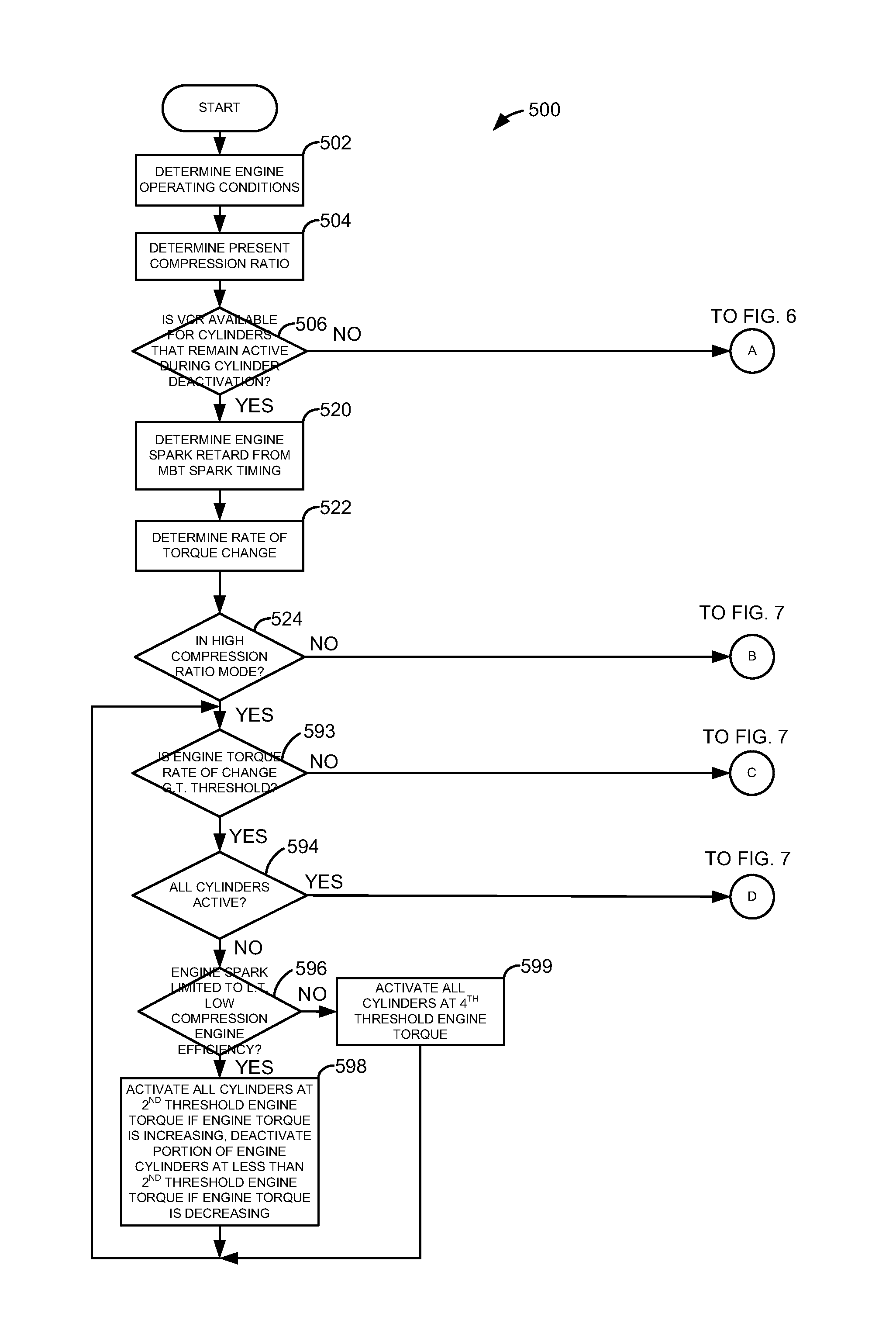
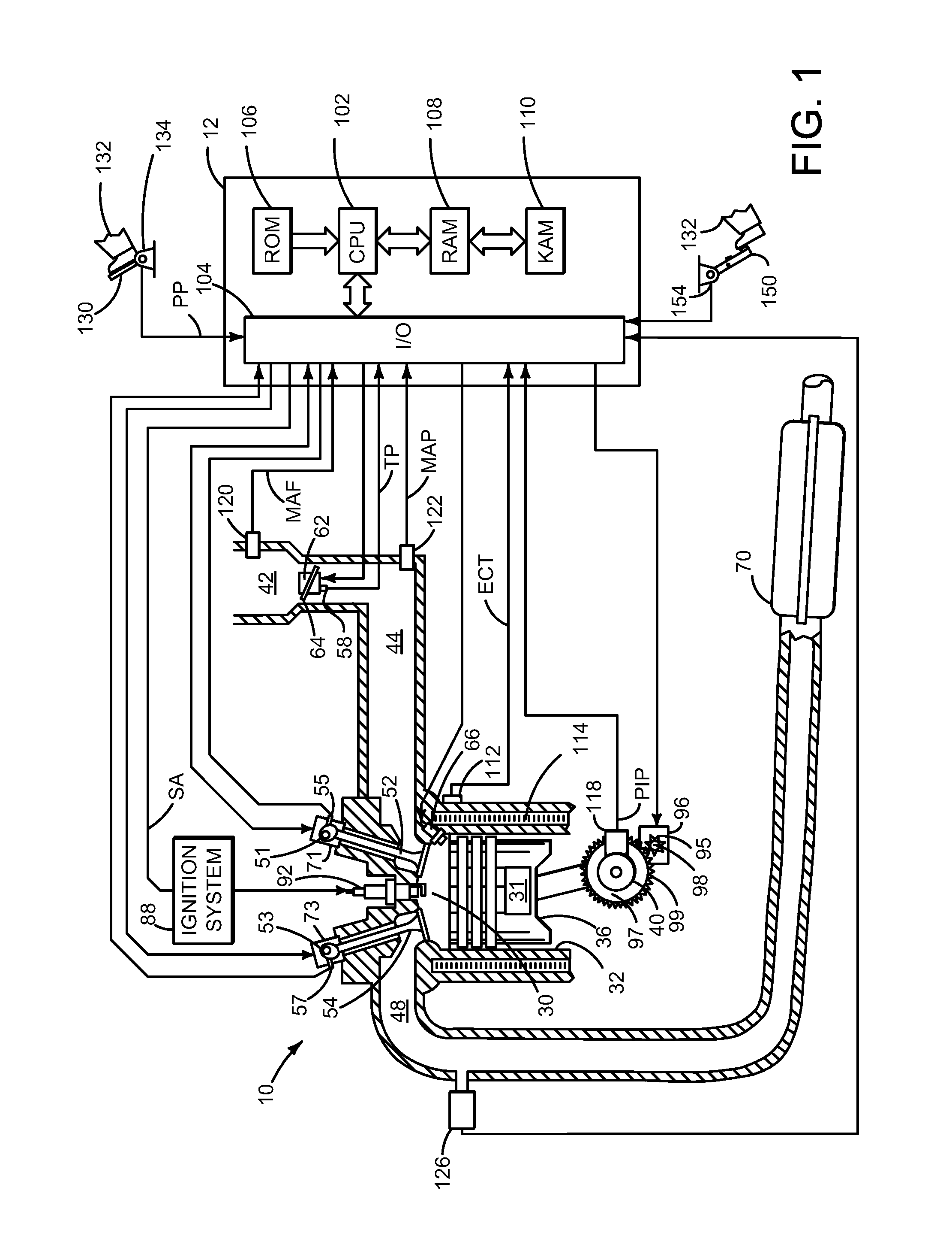
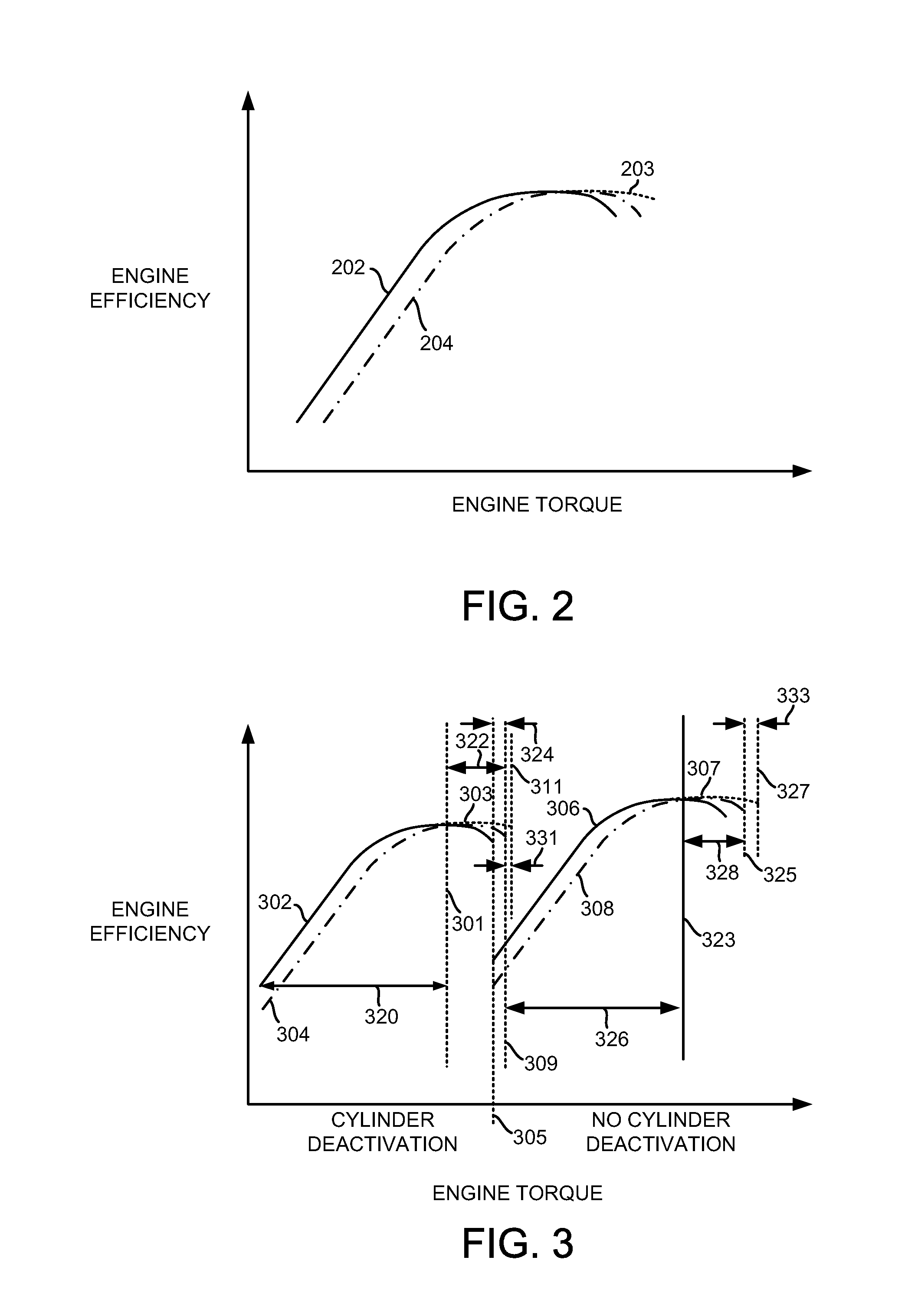
[0014]The present description is related to controlling operation of an engine that may selectively activate and deactivate cylinders to vary active cylinder displacement. The engine may also include capabilities for variable compression rates. FIG. 1 shows an example engine system that includes mechanisms for varying both active cylinder displacement and compression ratio. The engine may operate as indicated in the engine efficiency versus engine torque plots as shown in FIGS. 2 and 3. The engine may also operate as shown in the sequence shown in FIG. 4. FIGS. 5-8 are a flowchart of a method for operating an engine. The engine of FIG. 1 may be operated according to the method of FIGS. 5-8 to provide the sequence shown in FIG. 4.

[0015]Referring to FIG. 1, internal combustion engine 10, comprising a plurality of cylinders, one cylinder of which is shown in FIG. 1, is controlled by electronic engine controller 12. Engine 10 includes combustion chamber 30 and cylinder walls 32 with pis...


PUM


Abstract

Systems and methods for improving operation of an engine are presented. In one example, a threshold torque at which deactivated engine cylinders are reactivated is adjusted in response to a varying engine compression ratio. In other examples, the torque threshold is adjusted in response to a rate of change in engine torque and engine compression ratio.

Description

FIELD[0001]The present description relates to a system and methods for improving engine efficiency and performance. The systems and methods may be particularly useful for engines that include cylinder deactivation and variable compression ratio.BACKGROUND AND SUMMARY[0002]An engine of a vehicle may include cylinder deactivation to improve engine efficiency. Engine cylinders may be selectively activated and deactivated to reduce engine pumping losses and adjust engine torque output. The engine cylinders may be activated and deactivated based on an engine torque threshold. For example, if the desired engine torque is greater than a threshold torque, all engine cylinders may be activated. If desired engine torque is less than the threshold torque, a fraction of engine cylinders maybe activated. Thus, the threshold engine torque is a condition for selecting between differing active cylinder displacements. However, it may not be desirable for the engine to switch between different active...

Claims


Application Information

Patent Timeline
IPC IPC(8): F02D17/02
CPCF02D17/02
Inventor LEONE, THOMAS G.DOERING, JEFFREY ALLEN
Owner FORD GLOBAL TECH LLC
Why Eureka
Try Eureka