Radiator cooling fan replacement to increase engine efficiency

Inactive Publication Date: 2005-01-06
FATHI SAIED
View PDF15 Cites 3 Cited by
  • Summary
  • Abstract
  • Description
  • Claims
  • Application Information

AI Technical Summary

Benefits of technology

[0016] United Kingdom Patent No. 2,154,280, published Sept. 4, 1985, teaches an engine-driven positive displacement supercharger. The supercharger is driven through a belt from a pulley attached to an extension of the engine crankshaft by a free wheel hub. In operation, air enters a rotor through a rotatably adjustable valve. The air charge is expanded to fill the entire workspace and is later re-compressed to a volume matching that of the engine and delivered through an exchanger to the engine cylinders. Fuel may be injected into the air charge before, during or after the supercharger without departing from the desired effects of the invention.
[0017] European Patent No. 849,447, published Jun. 24, 1998, describes an arrangement for the indirect cooling of an internal combustion engine or a motor coach. The cooling system has an air-fluid heat exchanger in which the fluid flow is cooled by a forced air flow produced by a fan. The fan is in the form of a centrifugal turbine with its axis of rotation and axial intake lying perpendicular to a first wall, and its centrifugal outlet flow channeled so that it exits tangentially and perpendicular a second wall. Finally, European Patent No. 343,785, published Nov. 11, 1989, teaches a cooling system for an internal combustion engine.
[0018] None of the above inventions disclose a device that can increase the density of air at low engine rpm. None of the above inventions and patents, taken either singly or in combination, is seen to describe the instant invention as claimed. Thus, a radiator cooling fan replacement to increase engine efficiency solving the aforementioned problems is desired. SUMMARY OF THE INVENTION
[0019] The present invention is a supercharger that acts as a replacement for a conventional radiator fan and at the same time increases the density of the air flowing from the radiator to the engine block of a vehicle. The present supercharger is a multi-stage centrifugal air pump. The multi-stage centrifugal air pump increases the density of the air at low rpm, while conventional turbo and superchargers only increase the density of air at high rpm.
[0020] The multi-stage centrifugal air pump comprises a housing that is disposed around the rotating shaft of the engine block. A plurality of radial air chambers are located inside of the housing. Each of the air chambers are hollow and are connected to the adjacent air chambers by a narrow air passage. An air intake opening is disposed along an outer wall of the housing. The air intake opening allows air from the radiator to enter into the air chambers. The air pump also provides an air outlet for allowing the compressed air to exit the air pump and enter the engine block.
[0021] Each of the plurality of air chambers includes a plurality of rotating blades. The rotating blades provide the centrifugal energy that increases the density of the air traveling through the air pump. The air chambers located farthest from the center of the centrifugal air pump contain the most rotating blades. The air chamber located at the center of the air pump contains the least amount of rotating blades. Also, the blades in the air chamber farthest from the center of the air pump rotate at a higher speed than then blades located nearest the center of the air pump. The rotating blades force the air to move through each of the air chambers. The density of the air gradually increases as it moves from chamber to chamber.

Problems solved by technology

There is a serious drawback to turbochargers in that they are effectively operational at one third of redline round per minute (rpm), which means that it will take time to build up exhaust gas and to rotate the compressor turbine.
Another drawback is that exit air temperature is relatively higher due to the hot turbine environment.
Also, turbochargers require elaborate manufacturing and maintenance that will translate into higher costs to consumers.
Superchargers also require high manufacturing and maintenance.
None of the above inventions disclose a device that can increase the density of air at low engine rpm.

Method used


Image

  • Radiator cooling fan replacement to increase engine efficiency
  • Radiator cooling fan replacement to increase engine efficiency
  • Radiator cooling fan replacement to increase engine efficiency

Examples


Embodiment Construction

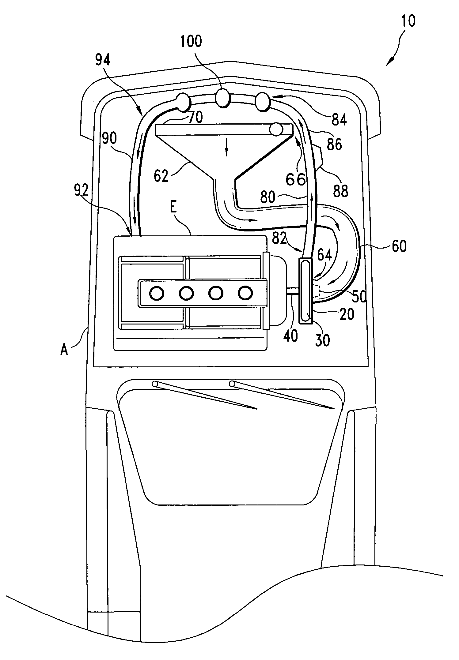
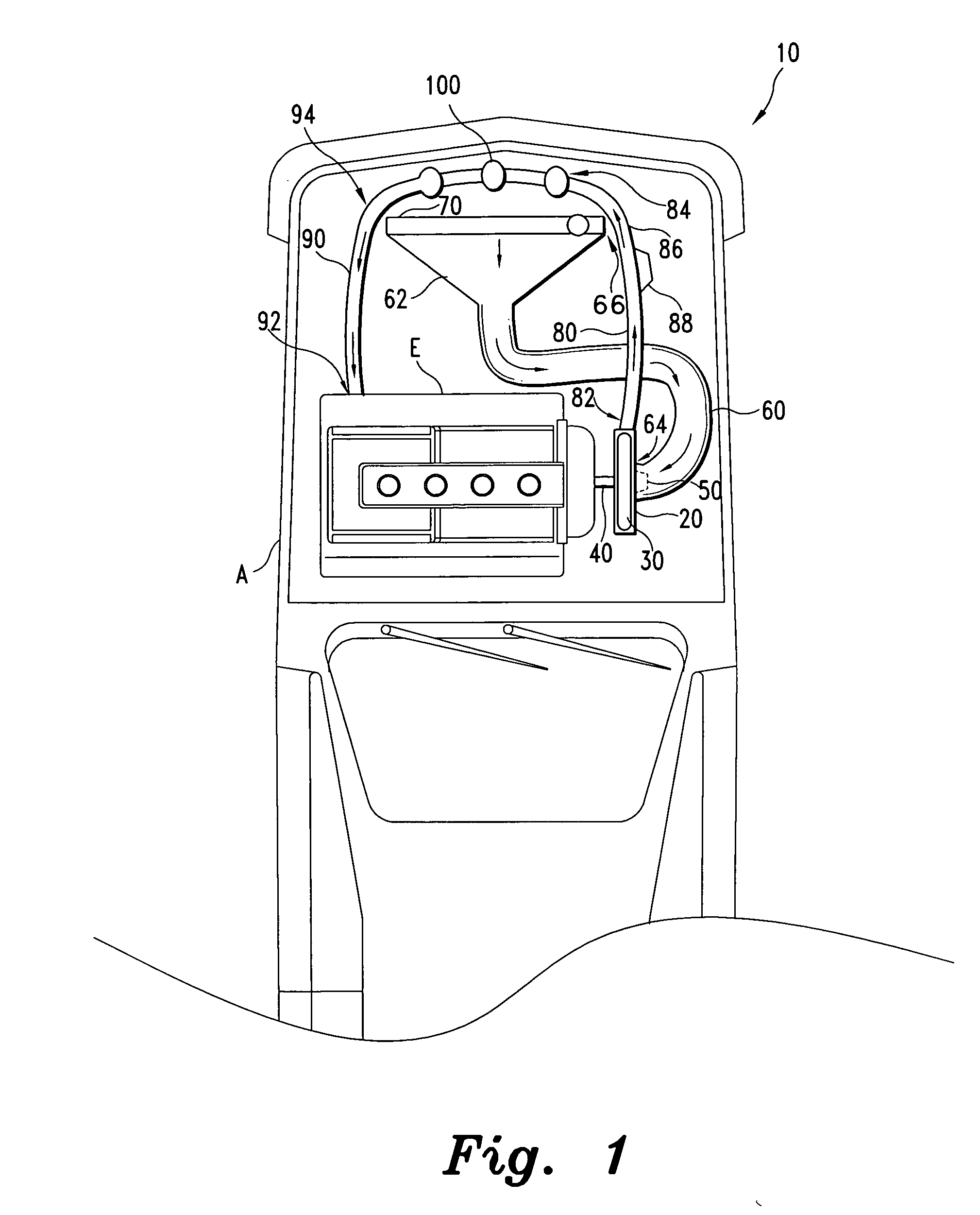
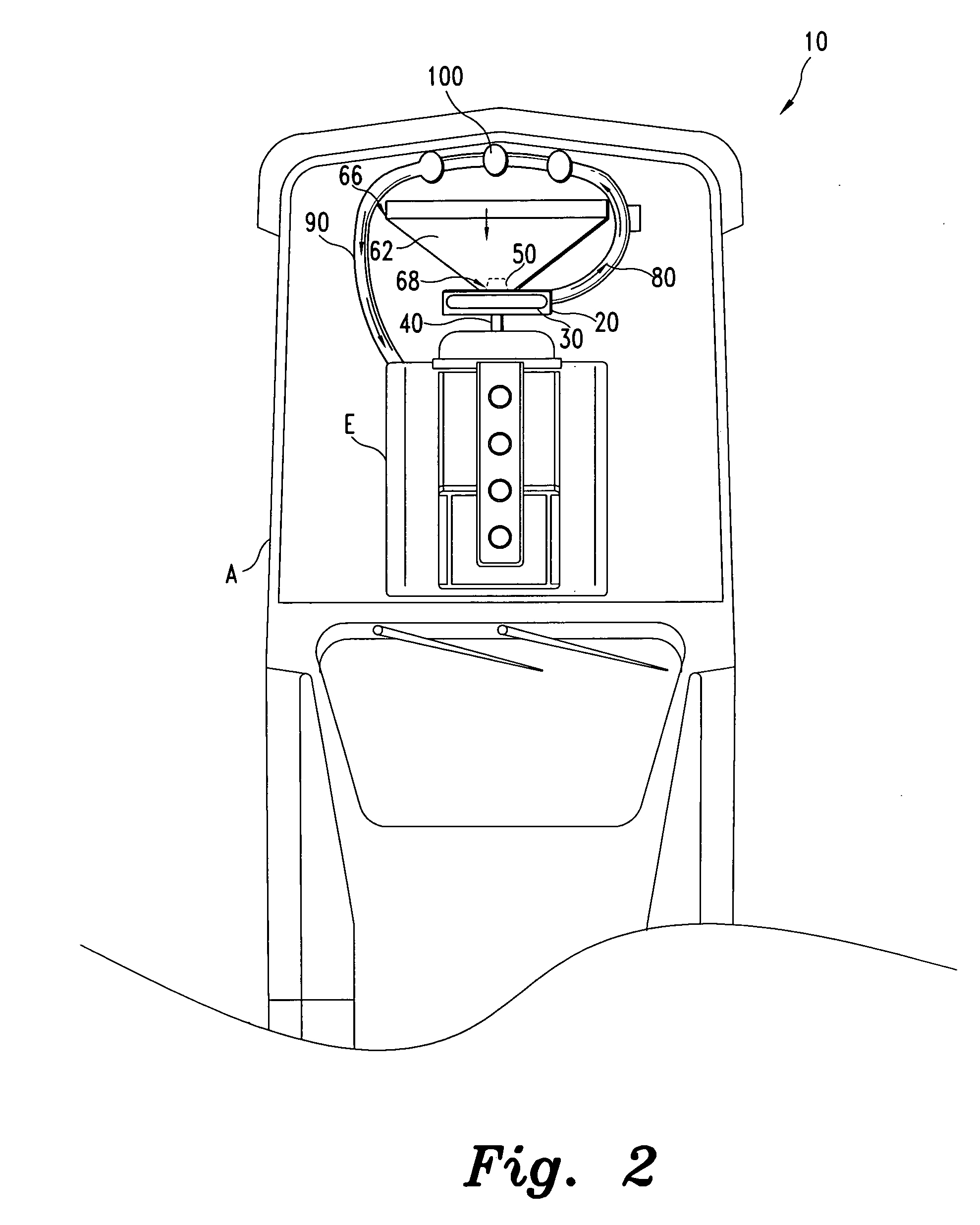
[0036] The present invention is a radiator fan cooling replacement that also acts as a supercharger for increasing the output of an internal combustion engine. The output of an engine is increased by increasing the size and the displacement of its pistons, which will increase the volume of air in the engine. To increase the output at a given volume of air, the density of the air must be increased. In other words, the mass of air must be increased at the same volume of air. The supercharger of the preferred embodiments of the present invention is a multi-stage centrifugal air pump that increases the density of the air in an internal combustion engine, while at the same time cooling the air so that the air pump may also act as a radiator fan replacement.

[0037]FIG. 1 depicts a top interior view of an automobile A with a radiator cooling fan replacement assembly 10. The radiator cooling fan replacement assembly 10 is secured to the output end of a conventional engine radiator 70. The r...


PUM


Abstract

The radiator cooling fan replacement to increase engine efficiency is a multi-stage centrifugal air pump supercharger that replaces the radiator fan while at the same time increases air density of its output air. The centrifugal air pump comprises a number of radial air chambers. Each air chamber includes a number of rotating blades. The rotating blades apply a centrifugal force to the air increasing the density of the air. The density of the air gradually increases as the air moves from one chamber to the next until it is forced out of the centrifugal air pump to the engine block. Before entering the engine block, the compressed air from the air pump passes through an air filter that cools the air.

Description

CROSS-REFERENCE TO RELATED APPLICATION [0001] This application claims the benefit of U.S. Provisional Patent Application Ser. No. 60 / 474,918, filed Jun. 3, 2003.BACKGROUND OF THE INVENTION [0002] 1. Field of the Invention [0003] The present invention relates to devices for increasing the density of air intake in internal combustion engines, and more particularly to a multi-stage centrifugal air pump that acts as a replacement for a conventional radiator fan, while at the same time having a high air density output applied to the air intake to effectively operate as a supercharger. [0004] 2. Description of the Related Art [0005] Increasing the mass of air into a cylinder of an internal combustion engine will increase its output. By increasing the piston size and its displacement the volume of air will increase. To increase the output at a given volume of air, the density of the charged air must be increased. Air density may be increased by supercharging or turbocharging. Turbochargers...

Claims


Application Information

Patent Timeline
IPC IPC(8): F01D1/06F01P5/02F02B29/04F02B33/40F02M35/024F04D29/32
CPCF01D1/06F01P5/02F02B29/0456Y02T10/146F02B33/40F02M35/024F04D29/325F02B29/0475Y02T10/12
Inventor FATHI, SAIED
Owner FATHI SAIED
Why Eureka
Try Eureka