Flex Flat Cable Structure and Electrical Connector Fix structure Thereof

Active Publication Date: 2018-03-08
KIM WELL ELECTRONICS INT
View PDF5 Cites 5 Cited by
  • Summary
  • Abstract
  • Description
  • Claims
  • Application Information

AI Technical Summary

Benefits of technology

[0014]Compared with the conventional technology, the present disclosure features that all of the signal lines are divided into a plurality of transmission line units in the FFC structure and the FFC electrical connector fix structure, and each of the plurality of transmission line units includes a first shield layer, a second shield layer, and a ground conductor. The first shield layer and the second shield layer have the ability of reflecting and absorbing electromagnetic waves. The ground conductor is arranged between the first shield layer and the second shield layer so that the first shield layer and the second

Problems solved by technology

When signals are transmitted at high speed, disturbance occurs between any neighboring signal lines.
As a result, the transmission quality of the signal line where sig

Method used


Image

  • Flex Flat Cable Structure and Electrical Connector Fix structure Thereof
  • Flex Flat Cable Structure and Electrical Connector Fix structure Thereof
  • Flex Flat Cable Structure and Electrical Connector Fix structure Thereof

Examples


Embodiment Construction

[0021]For better understanding embodiments of the present disclosure, the following detailed description taken in conjunction with the accompanying drawings is provided. Apparently, the accompanying drawings are merely for some of the embodiments of the present disclosure. Any ordinarily skilled person in the technical field of the present disclosure could still obtain other accompanying drawings without use laborious invention based on the present accompanying drawings.

[0022]The following descriptions of all embodiments, with reference to the accompanying drawings, are used to exemplify the present disclosure. Directional terms mentioned in the present disclosure, such as “top”, “bottom”, “front”, “back”, “left”, “right”, “inside”, “outside”, “side”, etc., are only used with reference to the orientation of the accompanying drawings. Therefore, the used directional terms are intended to illustrate, but not to limit, the present disclosure.

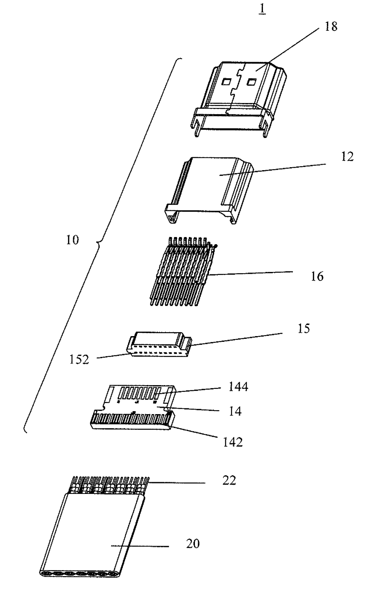
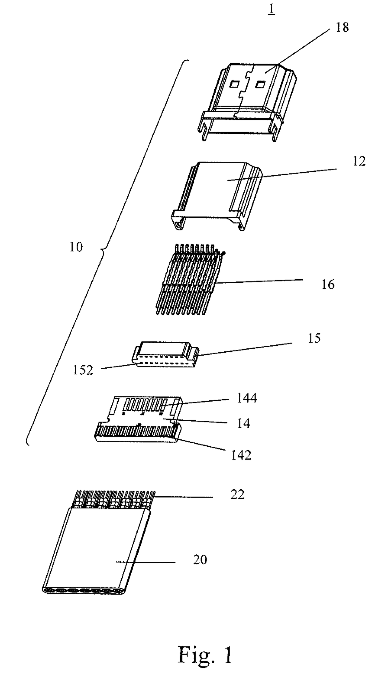
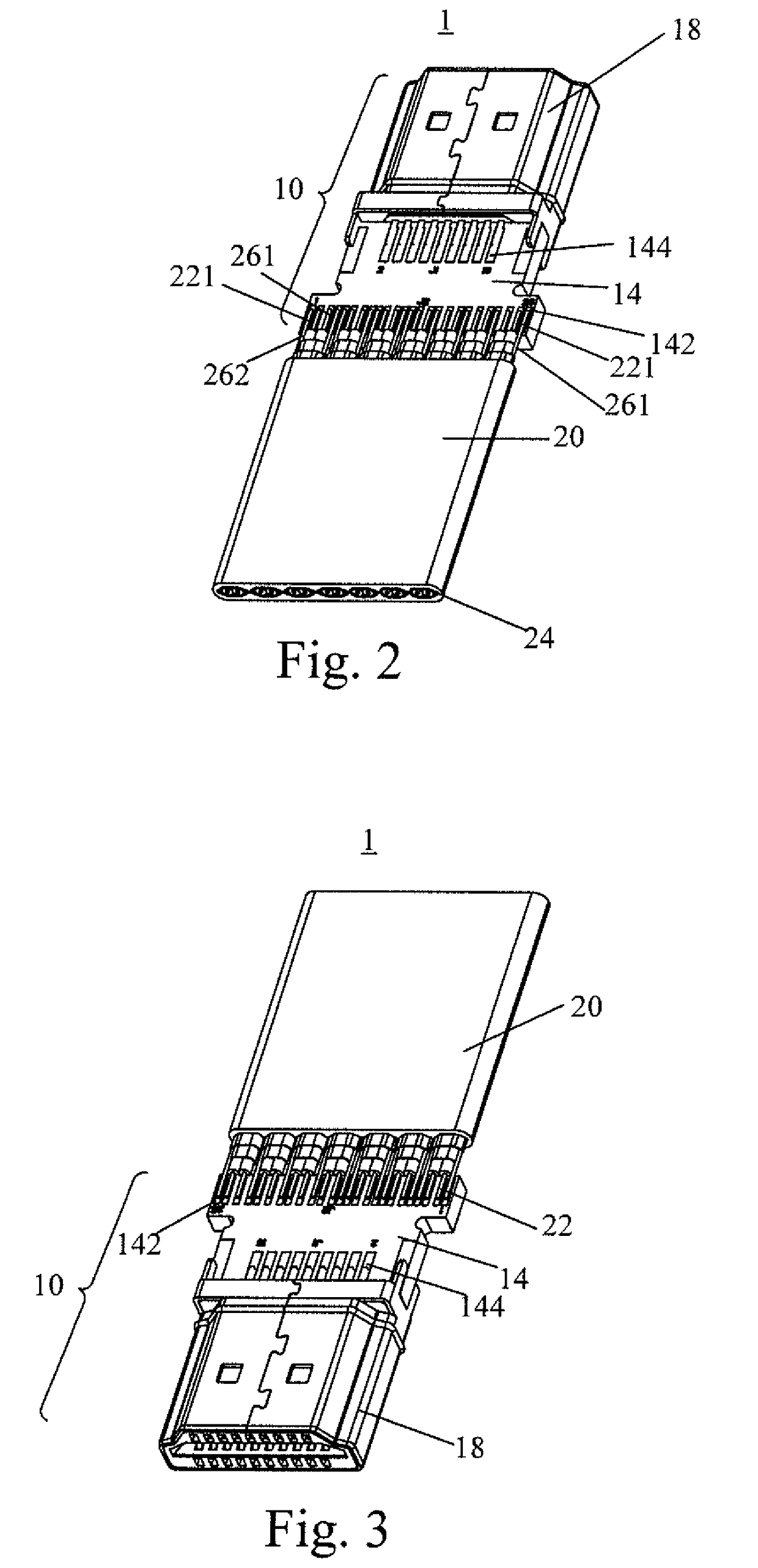
[0023]Refer to FIG. 1 to FIG. 4. FIG. 1 is a...


PUM

PropertyMeasurementUnit
Electrical conductoraaaaaaaaaa
Electric potential / voltageaaaaaaaaaa

Abstract

A FFC structure includes transmission line units and a second insulating jacket. The adjacent transmission line units are spaced. Each of the plurality of transmission line units includes one or more signal lines, a first shield layer, a first ground conductor, and a second shield layer. Each of the signal lines includes a signal conductor to transmit a data signal or a power, and a first insulating jacket enclosing the signal conductor. The first shield layer surrounds the signal line and is connected to the first insulating jacket of each of the signal lines. The first ground conductor transmits a ground voltage. The second shield layer surrounds and is connected to the first ground conductor and the first shield layer. The second insulating jacket encloses the second shield layer of the plurality of transmission line units.

Description

1. FIELD OF THE DISCLOSURE The present disclosure relates to a flex flat cable (FFC) structure, and more particularly, to an FFC structure designed to reduce electromagnetic interference (EMI).2. DESCRIPTION OF THE RELATED ART[0001]A flex flat cable (FFC) is a new type of data cable. The FFC is produced after an insulation material and an extremely thin tin-coated flat copper line are compressed using an automatic device. The merits of the FFC is neat arrangement, a large amount of transmission volume, flat structure, compactness, easy to dismantle, flexibility so the FFC, as a data transmission cable, can be applied to all kinds of electronic products easily and flexibly. Especially, the FFC can be used in the high-frequency bending condition such as the connection of mobile components. As for the way of connection, insertion with a connector and direct welding on a printed circuit board (PCB) are both possible.[0002]The tendency to design an electronic product is body's compactnes...

Claims


Application Information

Patent Timeline
IPC IPC(8): H01B7/08H01R12/77H01B3/30H01B7/04H01B7/02H01B9/00H01P3/02
CPCH01B7/0823H01R12/777H01B3/308H01B7/04H01B7/0861H01B7/0225H01B9/003H01P3/02H01B7/0216H01B11/203H01P5/085H01R12/598H01R12/62
Inventor CHIN, HSU-SHEN
Owner KIM WELL ELECTRONICS INT
Why Eureka
Try Eureka