Method for producing bent glass article, and bent glass article
- Summary
- Abstract
- Description
- Claims
- Application Information
AI Technical Summary
Benefits of technology
Problems solved by technology
Method used
Image

Examples
first configuration embodiment
of Support Jig
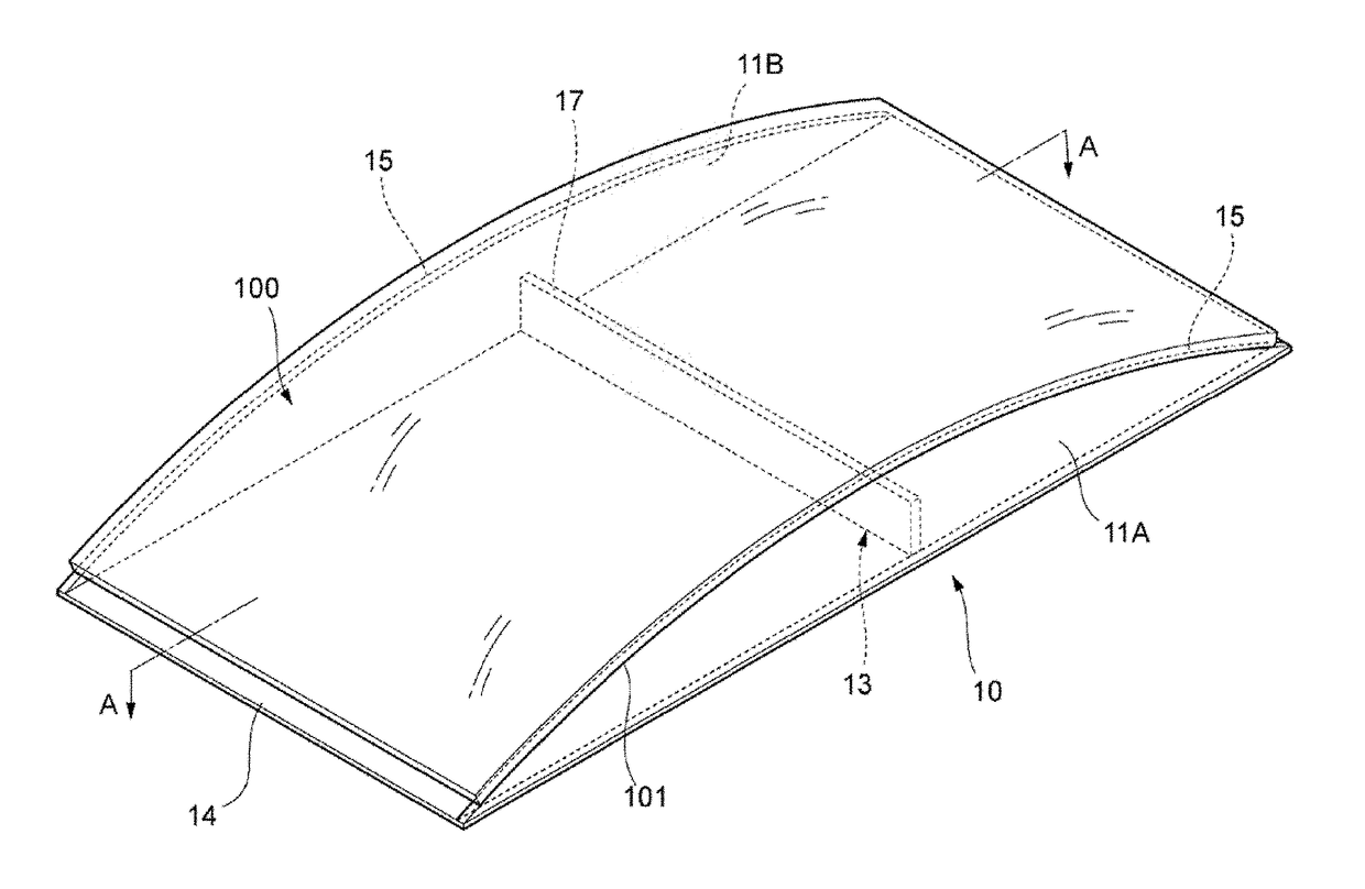
[0056]FIG. 3 shows a perspective view of the first configuration embodiment of a support jig for supporting a bent glass. A bent glass 100 in the embodiment is rectangular in top view. The bent glass 100 is formed so as to be curved along its long sides. The bent glass 100 is annealed in a state where a first main surface 101 which is a lower concave surface is supported by a support jig 10. The first main surface which is a surface which has been contacted with the molding surface of the mold does not have to be supported by the support jig 10 as described above. In some situation, a second main surface may be supported.
[0057]The support jig 10 in the embodiment includes a pair of support plates 11A and 11B disposed in parallel with each other, a connection plate 13 that connects the pair of support plates 11A and 11B with each other, and a base plate 14 that fixes the support plates 11A and 11B and the connection plate 13. The connection plate 13 or the base plate 14...
second configuration embodiment
of Support Jig
[0108]FIG. 6 is a perspective view of the second configuration embodiment of a support jig for supporting a bent glass. In the following description, members or parts that can be shared will be referenced correspondingly to each other, and description thereof will be omitted or simplified.
[0109]A support jig 20 in the embodiment includes a pair of support plates 21A and 21B disposed in parallel with each other, a connection plate 23 that connects the pair of support plates 21A and 21B with each other, and a base plate 14 that fixes the support plates 21A and 21B and the connection plate 23.
[0110]In the support plates 21A and 21B, mounting surfaces 25 in their upper end parts are formed into arc shapes. The support plates 21A and 21B are provided to stand perpendicularly to the base plate 14. By the mounting surfaces 25, the first main surface 101 of the bent glass 100 are supported from below at both end parts on the side of the long-side of the bent glass 100. Each mo...
third configuration embodiment
of Support Jig
[0113]FIG. 7 is a perspective view of the third configuration embodiment of a support jig for supporting a bent glass.
[0114]A support jig 30 in the configuration embodiment includes a connection plate 33 including a pair of support pins 31A and 31B for supporting the first main surface 101 of the bent glass 100 from below, and a base plate 14 that fixes the connection plate 33. The base plate 14 may be shortened or omitted as long as the connection plate 33 can be fixed erectly.
[0115]By the support pins 31A and 31B, an intermediate part of the bent glass 100 in its long-side direction is supported at both end parts in its short-side direction. That is, each of the pair of support pins 31A and 31B supports the bent glass 100 in a higher position than an end part in the long-side direction corresponding to the lowest position of the first main surface 101 of the bent glass 100.
[0116]When the heights of the support pins 31A and 31B are adjusted, the support jig 30 in the ...
PUM
| Property | Measurement | Unit |
|---|---|---|
| Fraction | aaaaa | aaaaa |
| Pressure | aaaaa | aaaaa |
| Pressure | aaaaa | aaaaa |
Abstract
Description
Claims
Application Information
 - R&D Engineer
- R&D Manager
- IP Professional
- Industry Leading Data Capabilities
- Powerful AI technology
- Patent DNA Extraction
Browse by: Latest US Patents, China's latest patents, Technical Efficacy Thesaurus, Application Domain, Technology Topic.
© 2024 PatSnap. All rights reserved.Legal|Privacy policy|Modern Slavery Act Transparency Statement|Sitemap