Inverted pendulum vehicle

a technology of pendulum and vehicle, which is applied in the direction of friction roller based transmission, cycle equipment, cycle stands, etc., can solve the problem that the vehicle may not be able to ride over the step

Inactive Publication Date: 2018-04-26
HONDA MOTOR CO LTD
View PDF8 Cites 6 Cited by
  • Summary
  • Abstract
  • Description
  • Claims
  • Application Information

AI Technical Summary

Benefits of technology

[0006]In view of such a problem of the prior art, a primary object of the present invention is to provide an inverted pendulu

Problems solved by technology

As a result, the vehicle may not be able to ride over the ste

Method used


Image

  • Inverted pendulum vehicle
  • Inverted pendulum vehicle
  • Inverted pendulum vehicle

Examples


first embodiment

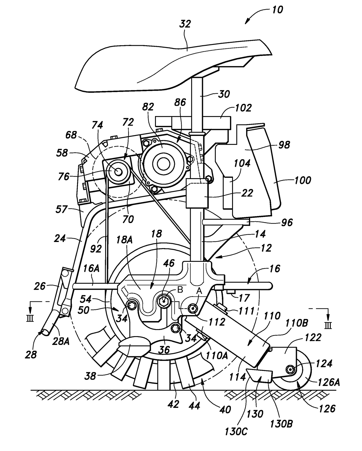
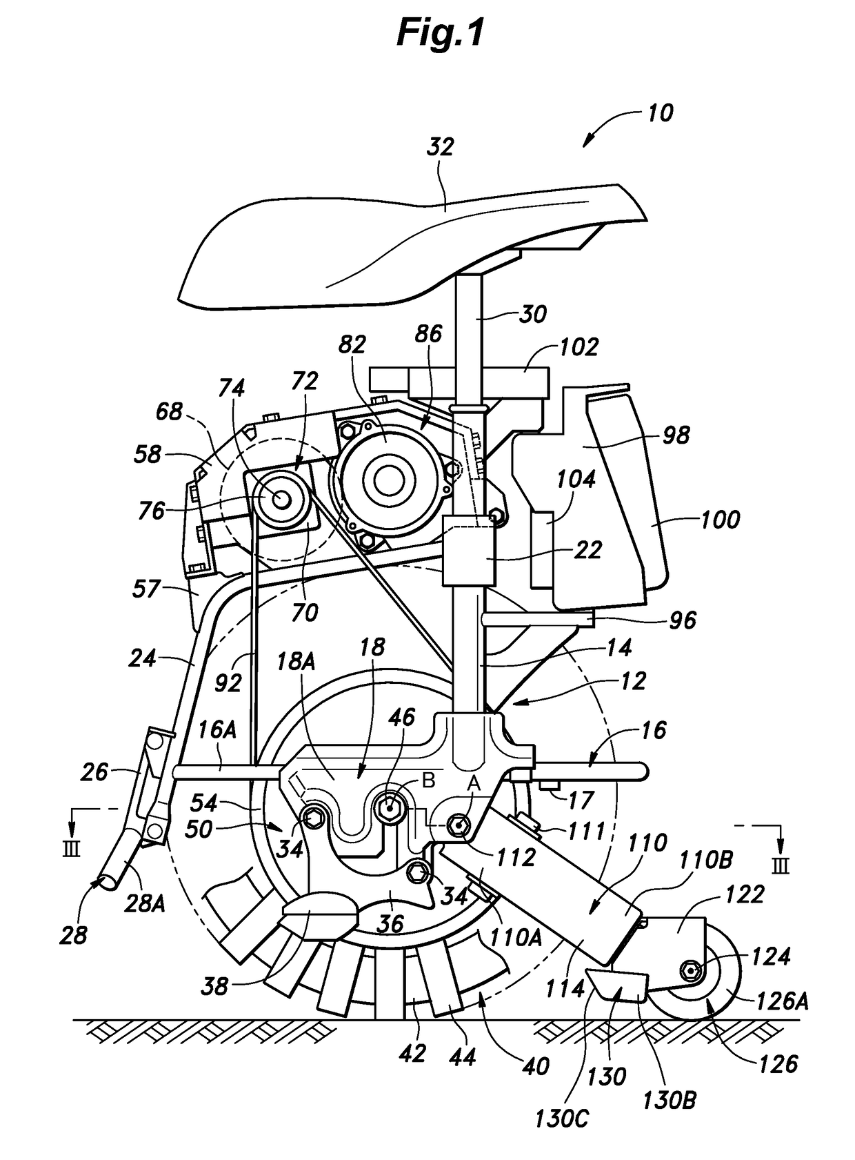
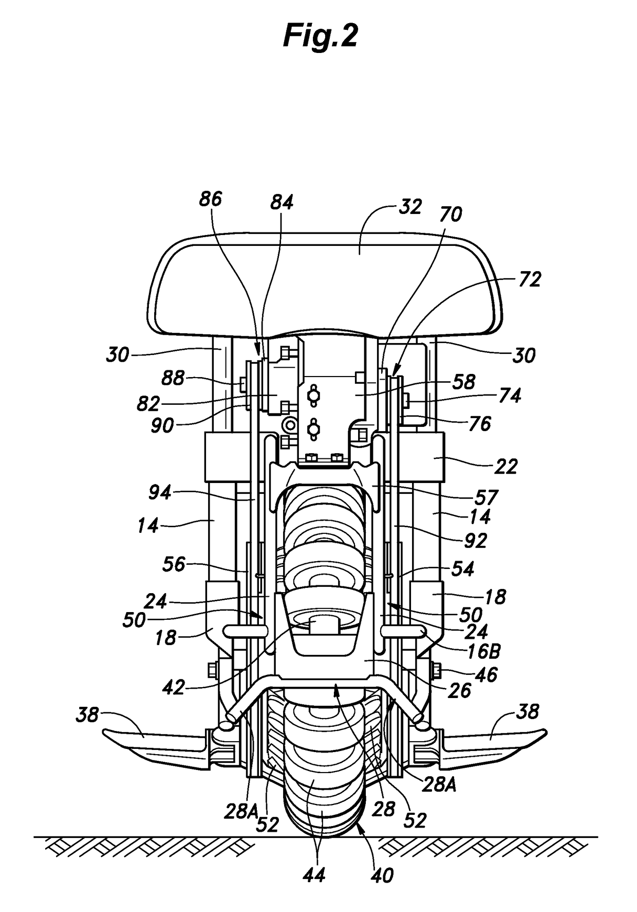
[0030]an inverted pendulum vehicle according to the present invention is described in the following with reference to FIGS. 1 to 6. The directions mentioned in the following description are based on the viewpoint of a rider seated on the inverted pendulum vehicle.

[0031]As shown in FIGS. 1 to 6, the inverted pendulum vehicle 10 includes a vehicle body frame 12 made of pipe members. The vehicle body frame 12 includes a pair of main posts 14 located on either side of the vehicle, a lower pipe member 16 including a pair of side member sections 16A extending along either side of the vehicle and joined to the lower ends of the respective main posts 14 at intermediate points thereof, and a rear cross member section 16B extending between rear ends of the two side member sections 16A, a pair of lower plates 18 extending downward from the respective side member sections 16A of the lower pipe member 16, a main cross member 22 extending between intermediate points of the main posts 14, and a pa...


PUM


Abstract

An inverted pendulum vehicle has a vehicle body frame, a main wheel combining a plurality of driven rollers arranged along a circle, a pair of drive disks rotatably supported by the vehicle body frame around a laterally extending rotational center line, a plurality of drive rollers arranged rotatably on each drive disk along a circumferential direction and configured to engage the driven rollers of the main wheel, a drive unit for individually driving the drive disks, a control unit for controlling the drive units under an inverted pendulum control, a tail wheel arm having a base end pivotally attached to a part of the vehicle body frame around a laterally extending pivot center line, a tail wheel rotatably supported by the tail wheel arm and a skid member attached to the tail wheel arm, the skid member including a pair of side walls slanting outward toward upper edges thereof.

Description

TECHNICAL FIELD[0001]The present invention relates to an inverted pendulum vehicle, and in particular to an inverted pendulum vehicle having a main wheel operating under an inverted pendulum control and a tail wheel positioned behind the main wheel.BACKGROUND ART[0002]JP2013-237327A and JP2014-234036A disclose an inverted pendulum vehicle comprising a vehicle body frame, a main wheel combining a plurality of driven rollers arranged along a circle such that the rotational center lines of the driven rollers are each directed along the tangential line of the circle, a pair of drive disks each carrying a plurality of drive rollers configured to engage the driven rollers of the main wheel, a pair of drive units including a pair of electric motors for individually driving the drive disks under an inverted pendulum control, a battery mounted on the vehicle body frame to supply electric power to the electric motors, and a saddle mounted on the vehicle body frame for seating a rider. To enab...

Claims


Application Information

Patent Timeline
IPC IPC(8): B62K11/00B62K1/00B62M13/00B62M7/10
CPCB62K11/007B62K1/00B62M13/00B62M7/10B62J99/00B62K3/00B62K17/00B62J45/00B62H1/10
Inventor INADA, JUNYOSHINO, TSUTOMUYADA, WATARUIWAKAMI, HIROSHI
Owner HONDA MOTOR CO LTD
Why Eureka
Try Eureka