
Battery and method of manufacturing the same

a battery and manufacturing method technology, applied in the field of batteries, can solve the problems of easy lowering of battery performance, insufficient junction areas between particles, and difficult to meet the requirements of battery performance, and achieve the effects of reducing the number of particles, and reducing the number of ion channels

Inactive Publication Date: 2018-05-03
MURATA MFG CO LTD
View PDF5 Cites 2 Cited by
  • Summary
  • Abstract
  • Description
  • Claims
  • Application Information

AI Technical Summary

Benefits of technology

[0012]In a battery using an electrolytic solution, an electrode (gaps between particles such as an active material) are impregnated with the electrolytic solution, and therefore, junction areas between the particles are increased. In this case, since sufficient ionic conduction is obtained between the particles, interface resistance does not become problematic. In contrast, in a battery using a solid electrolyte, a medium such as an electrolytic solution does not exist between particles, and therefore, junction areas between the particles are not sufficient. In this case, sufficient ionic conduction is not obtained between the particles, and therefore, interface resistance becomes problematic. That is, the interface resistance between the particles is increased, and therefore, lowering of battery performance easily occurs.
[0015]According to the battery according to the embodiment of the present technology, one or more of the cathode, the anode, and the solid electrolyte layer include a solid electrolyte binder, and therefore, ionic conduction is allowed to be improved. Further, according to the method of manufacturing the battery according to the embodiment of the present technology, after one or more of the cathode preparatory body and the like are formed to include the solid electrolyte binder, one or more of the cathode and the like are formed by heating the solid electrolyte binder, and therefore, a battery having improved ionic conduction is allowed to be manufactured.

Problems solved by technology

In contrast, in a battery using a solid electrolyte, a medium such as an electrolytic solution does not exist between particles, and therefore, junction areas between the particles are not sufficient.
In this case, sufficient ionic conduction is not obtained between the particles, and therefore, interface resistance becomes problematic.
That is, the interface resistance between the particles is increased, and therefore, lowering of battery performance easily occurs.

Method used

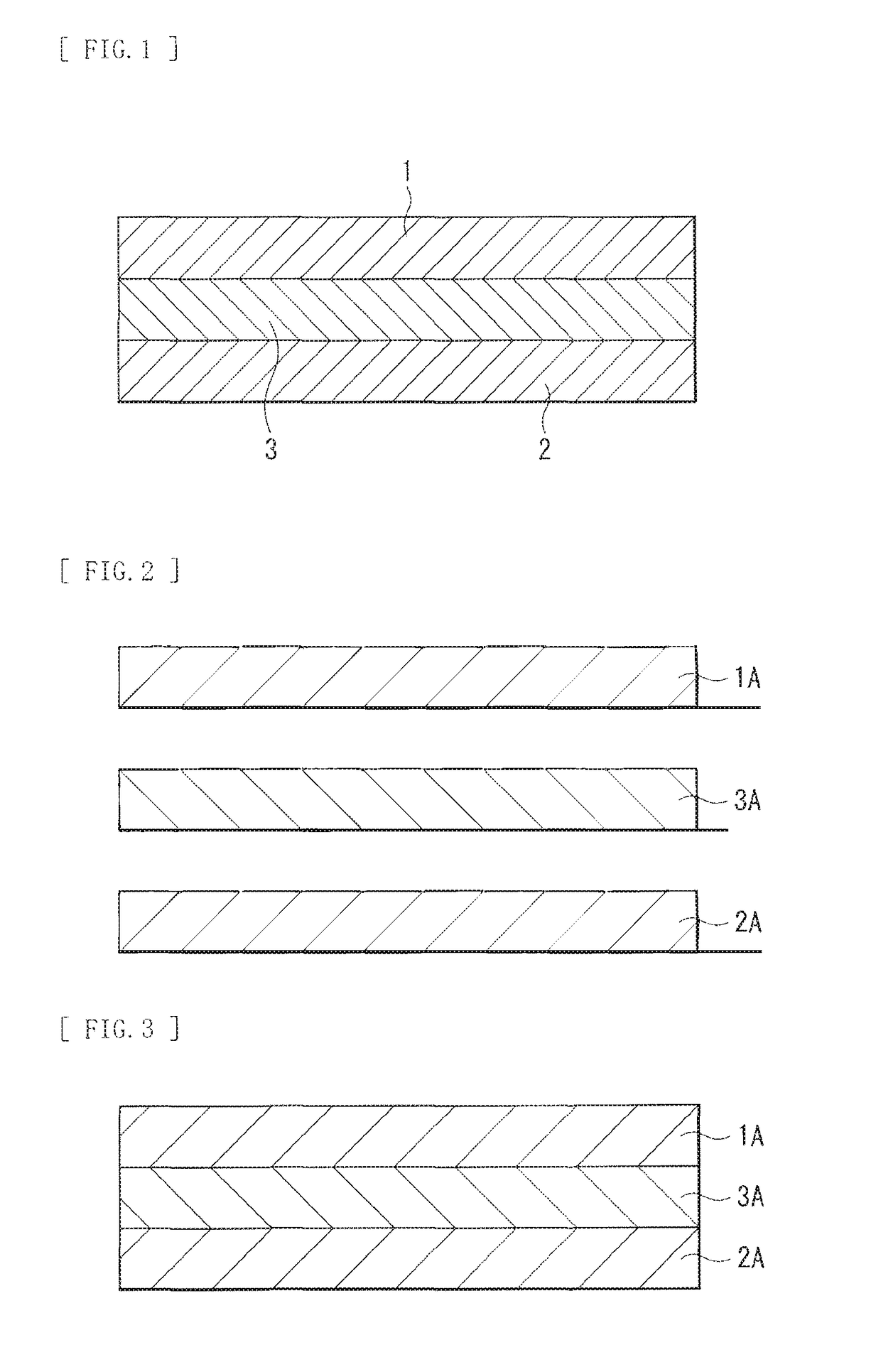

Image

  • Battery and method of manufacturing the same
  • Battery and method of manufacturing the same

Examples


examples

[0080]Description will be given for details of specific examples of the present technology.

examples 1 to 3

[0081]Pellet samples for measuring physical properties of solid electrolytes were fabricated by the following procedure, and ionic conduction thereof was compared to one another.

[0082]As illustrated in Table 1, as necessary, powder of an additive was added to powder of a solid electrolyte (Li1.3Al0.3Ti1.7(PO4)3: LATP). Subsequently, the resultant powder mixture was formed into a state of a pellet with the use of an oil pressing machine (pressure: 10 MPa). In these examples, B2O3 or a compound (an Li—B—O compound) having an Li—B—O bond was used as an additive, and the additive amount was 1 wt % with respect to the amount (100 wt %) of an active material. It is to be noted that in the case where the Li—B—O compound was formed, a cooling method was used, and the mixture ratio between Li2O and B2O3 was Li2O:B2O3=42.7:57.3. Subsequently, the resultant formed body was heated (at 475deg C. for 12 hours) in the atmosphere to obtain a test pellet sample. In these examples, when differential ...


PUM

PropertyMeasurementUnit
pressureaaaaaaaaaa
crystallization onset temperatureaaaaaaaaaa

Abstract

A battery capable of improving ionic conduction is provided. The battery includes a cathode, an anode, and a solid electrolyte layer. One or more of the cathode, the anode, and the solid electrolyte layer includes a solid electrolyte binder.

Description

CROSS-REFERENCE TO RELATED APPLICATION[0001]The present application is a continuation application of U.S. patent application Ser. No. 14 / 347,125, filed Mar. 25, 2014, which is a national stage entry of PCT / JP2012 / 075103, filed Sep. 28, 2012, which claims priority from prior Japanese Priority Patent Application JP 2011-221978 filed in the Japan Patent Office on Oct. 6, 2011, the entire contents of which are hereby incorporated by reference.TECHNICAL FIELD[0002]The present technology relates to a battery including a cathode, an anode, and a solid electrolyte layer and to a method of manufacturing the same.BACKGROUND ART[0003]In recent years, as various electronic apparatuses have been widely used, demand for batteries as electric power sources thereof have been rapidly expanded. Applications of the electronic apparatuses are not limited to small-sized applications such as a mobile phone and a notebook-size personal computer, and include a wide variety of applications to large-sized ap...

Claims


Application Information

Patent Timeline
Patent Type & Authority Applications(United States)
IPC IPC(8): H01M10/0562H01M4/62H01M10/052H01M10/0585
CPCH01M4/62H01M2300/0068H01M10/052H01M10/0585H01M10/0562Y02T10/7011Y02E60/10Y02P70/50Y02T10/70
Inventor FURUKAWA, KEIKOFURUYA, TATSUYA
Owner MURATA MFG CO LTD
Learn More