Rotary electric machine

a rotary electric machine and electric motor technology, applied in the direction of dynamo-electric machines, magnetic circuit rotating parts, magnetic circuit shapes/forms/construction, etc., can solve the problem of reducing the torque of the rotary electric machine, and achieve the effect of suppressing the torque decrease and suppressing the damage to the center bridg

Active Publication Date: 2018-05-24
TOYOTA JIDOSHA KK
View PDF4 Cites 20 Cited by
  • Summary
  • Abstract
  • Description
  • Claims
  • Application Information

AI Technical Summary

Benefits of technology

[0007]In a two-layered embedded magnet type rotor, the length along the circumferential direction of a permanent magnet of a layer on the inner peripheral side is longer than the length along the circumferential direction of a permanent magnet of a layer on the outer peripheral side. Therefore, when the width of a magnetic path which is formed between the permanent magnet of the layer on the outer peripheral side and the permanent magnet of the layer on the inner peripheral side is constant along the circumferential direction, when a magnetic flux passing through the permanent magnet of the layer on the inner peripheral side is directed to the permanent magnet of the layer on the outer peripheral side, local denseness of magnetic fluxes can occur. If the magnetic fluxes passing through the magnetic path locally gather densely, saturation of magnetic flux density occurs, and thus there is a possibility that the torque of the rotary electric machine may decrease. Therefore, a rotary electric machine is desired in which in the two-layered embedded magnet type rotor, the saturation of the magnetic flux density is relieved, and thus a decrease in torque can be suppressed.
[0009]According to the rotary electric machine of the aspect of the disclosure, the angle that each of the permanent magnets of a layer on the outer peripheral side makes with the magnetic pole center is larger than the angle that each of the permanent magnets of a layer on the inner peripheral side makes with the magnetic pole center. In this way, with respect to a magnetic path between the two layers, the magnetic path on the magnetic pole center side becomes wider than the magnetic path on the magnetic pole end side, and therefore, it is possible to relieve saturation of magnetic flux density in the magnetic path between the two layers and suppress a decrease in torque of the rotary electric machine.
[0015]The stress acting due to a centrifugal force or an excitation force due to the rotation of the rotary electric machine increases as the size of each of the permanent magnets which are embedded becomes larger. According to the rotary electric machine of the aspect of the disclosure, the length of the center bridge on the inner peripheral side where the number of magnets is larger in the two layers is longer than the length of the center bridge on the outer peripheral side, and therefore, the stress taken on the center bridge on the outer peripheral side and the stress taken on the center bridge on the inner peripheral side are equalized, and thus damage to the center bridges can be suppressed.

Problems solved by technology

If the magnetic fluxes passing through the magnetic path locally gather densely, saturation of magnetic flux density occurs, and thus there is a possibility that the torque of the rotary electric machine may decrease.

Method used


Image

  • Rotary electric machine
  • Rotary electric machine
  • Rotary electric machine

Examples


Embodiment Construction

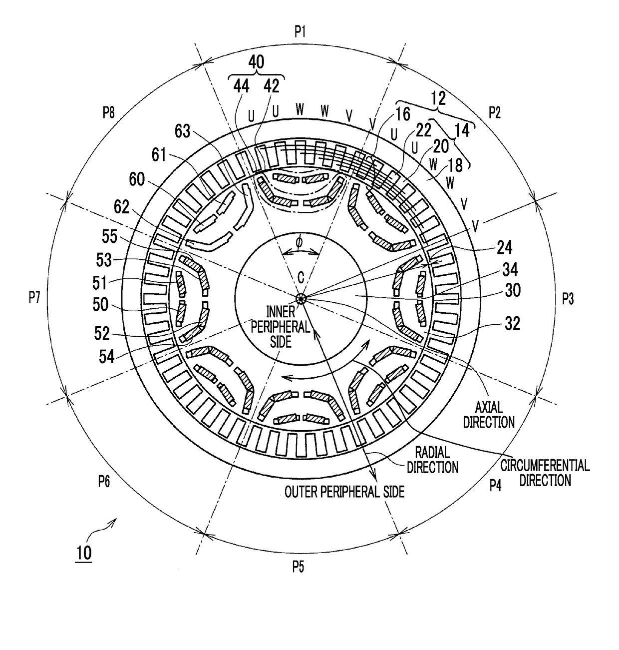
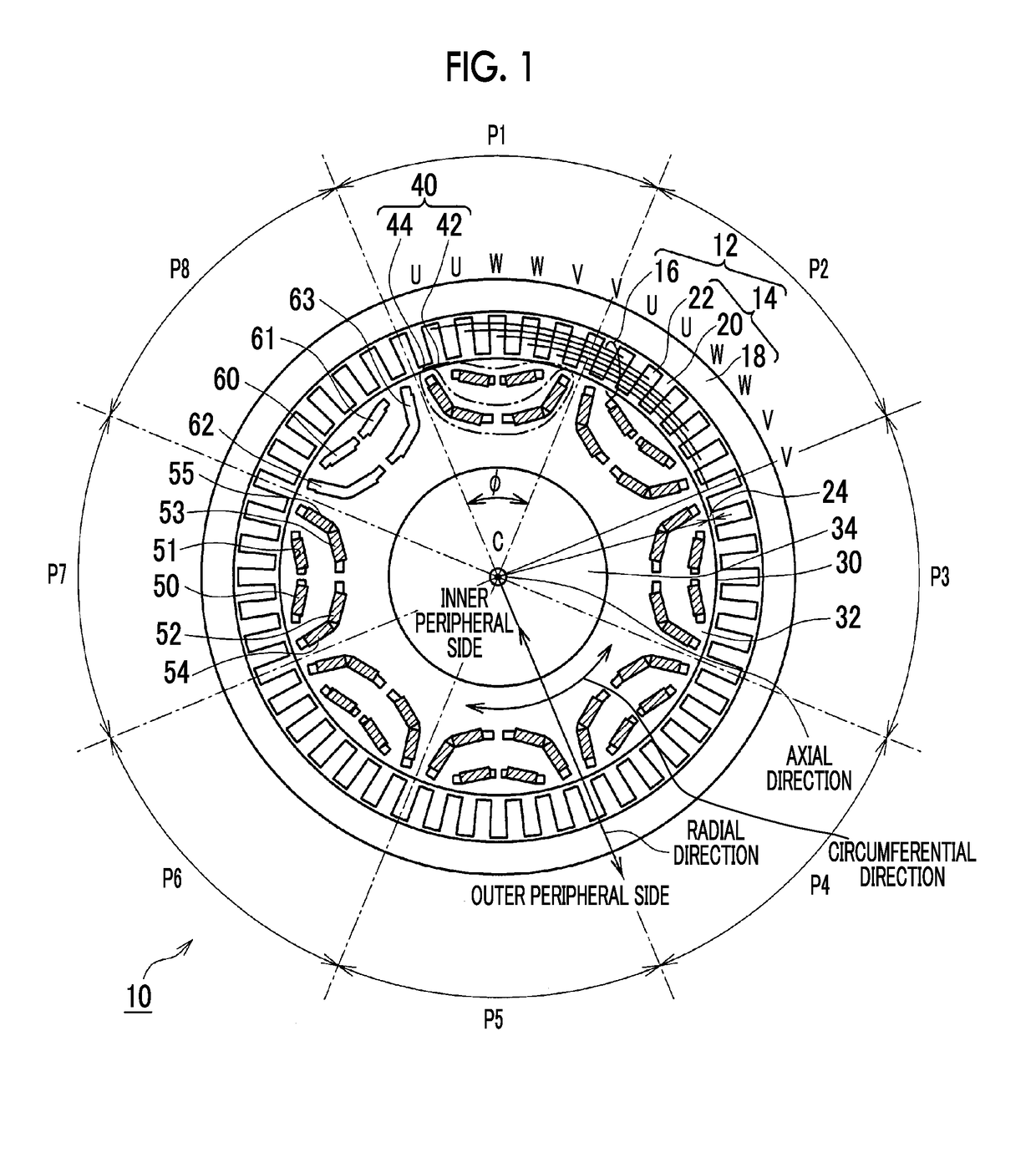
[0025]Hereinafter, an embodiment related to the disclosure will be described in detail using the drawings. In the following, a rotary electric machine which is mounted on a vehicle will be described. However, this is merely an example for explanation, and the rotary electric machine may be used for uses other than mounting on a vehicle. In the following, a method of winding a stator coil will be described as distributed winding. However, this is merely an example for explanation, and the winding method may be concentrated winding.

[0026]The shapes, the dimensions, the number of teeth, the number of slots, the number of magnetic poles of a rotor, the number of permanent magnets, the material, and the like, which are described below, are merely examples for explanation and can be appropriately changed in accordance with the specifications of a rotary electric machine. In the following, in all the drawings, the same elements are denoted by the same reference numerals, and overlapping de...


PUM


Abstract

A rotary electric machine includes a stator and a rotor. The rotor includes a rotor core and a plurality of permanent magnets. The permanent magnets are disposed to be divided into two layers, the two layers being a layer on the outer peripheral side and a layer on the inner peripheral side of the rotor core, and the permanent magnets are disposed line-symmetrically with respect to a magnetic pole center of the rotor core and in a V-shape or a U-shape in each of the two layers. An angle that each of the permanent magnets disposed on the outer peripheral side makes with the magnetic pole center of the V-shape or the U-shape is larger than an angle that each of the permanent magnets disposed on the inner peripheral side makes with the magnetic pole center of the V-shape or the U-shape.

Description

INCORPORATION BY REFERENCE[0001]The disclosure of Japanese Patent Application No. 2016-222475 filed on Nov. 15, 2016 including the specification, drawings and abstract is incorporated herein by reference in its entirety.BACKGROUND1. Technical Field[0002]The disclosure relates to a rotary electric machine and in particular, to a rotary electric machine which is provided with an embedded magnet type rotor.2. Description of Related Art[0003]With respect to a rotary electric machine which is used in an electric vehicle, in order to attain reduction in size and weight and improvement in output efficiency, an embedded magnet type rotary electric machine is used in which a plurality of permanent magnets is embedded along a circumferential direction in a rotor core to form magnetic poles. The embedded magnet type rotary electric machine outputs combined torque of magnetic torque which is generated by cooperation of a rotating magnetic field of a stator with the permanent magnets and relucta...

Claims


Application Information

Patent Timeline
Patent Type & Authority Applications(United States)
IPC IPC(8): H02K1/27
CPCH02K1/2766H02K2213/03
Inventor HATTORI, HIROYUKI
Owner TOYOTA JIDOSHA KK
Why Eureka
Try Eureka