Angularly Adjustable Balancing Device

a balancing device and adjustable technology, applied in the field of balancing devices, can solve the problems of not allowing the balancing of stationary items, reducing the utility and entertainment value of such efforts, and not also allowing the user to choose various objects

Active Publication Date: 2018-08-09
MACHADO GAMERO LUIS GERARDO
View PDF7 Cites 13 Cited by
  • Summary
  • Abstract
  • Description
  • Claims
  • Application Information

AI Technical Summary

Benefits of technology

[0012]The present invention is directed to a balancing device that, in one or more aspects, supports a variety of objects at an equilibrium balancing angle that is adjustable without adjusting, changing, or combining counterweights, utilizes a magnetic attachment between a balance member and object to be balanced, utilizes a pointed spike and concave depression arrangement between a balance member affixed to the object and stand therefor, maintains an equilibrium balancing angle without requiring an object to be spun, and allows and object to freely spin about a point.
[0014]In use, a user selects an object to be balanced, such as a plate, panel, board, or even bottle and affixes the ferrous metal plate to the surface thereof so the ferrous metal plate is preferably near a point vertically in line with the object's center of gravity. For example, the user may clamp the ferrous metal plate to a U-shaped board so the ferrous metal plate located at a point within the legs and base of the shape corresponding with its center of gravity. Once affixed, the user then magnetically attaches the balance member to a point on a surface of the ferrous metal plate and places the balance member and object upon the support so that the pointed spike rests within the concave recess thereof. Upon placement, the object will naturally come to rest at an equilibrium angle based on the location of the balance member with respect to the ferrous metal plate and the center of gravity of the object. A user can then adjust the equilibrium balancing angle, as desired, by altering the location of the balance member on the ferrous metal plate. In addition, the object may be freely rotated about the support. An object, so supported may thereby remain balanced on a particular point at a particular angle so long as the spoke and concave recess remains vertically in-line with the object's center of gravity.
[0015]Thereby, with a balancing device as described, a user may balance an object for entertainment and enjoyment purposes. For example, a user may choose to balance a game board, so placement of game pieces thereupon may provide an entertaining and challenging feature to the game. In an additional example, a user may choose to balance a bottle so that bottle may pivot and freely spin about a point and the motion of the bottle may provide entertainment—such as being utilized in the classic game of spin-the-bottle—or be utilized for pouring a substance contained therein in a novel and entertaining way.

Problems solved by technology

However, many such devices commonly require rotation at a particular speed to be balanced on a tip, thereby not allowing balancing of a stationary item.
Even if they do allow balancing of a stationary item, such devices commonly require engagement of the tip in a way that limits the motion of the device, such as not allowing the device to be freely spun about a point.
Further, even if such devices do not require rotation to balance and allow the free motion of the device, it is uncommon for such devices to allow variation of the angle at which the device is balanced by any other means that adjustment, changing, or combining or counterweights.
Lastly, no matter how such devices are balanced, many such devices commonly do not also allow a user to choose various objects to be supported.
However, these earlier efforts suffer from one or more of the following disadvantages, which decrease the utility and entertainment value of such efforts: they are limited in what objects may be angularly balanced, they do not allow for adjustment of the equilibrium balancing angle of an object affixed thereto without adjusting, changing, or combining counterweights, they do not utilize a pointed spike and concave depression arrangement between their balance members and supports, they do not utilize magnets to connect a balance member to an object and maintain the equilibrium balancing angle, they are not able to balance without spinning, and they do not allow an object to freely move about a point upon which it is supported.

Method used


Image

  • Angularly Adjustable Balancing Device
  • Angularly Adjustable Balancing Device
  • Angularly Adjustable Balancing Device

Examples


first embodiment

of the Method of Use

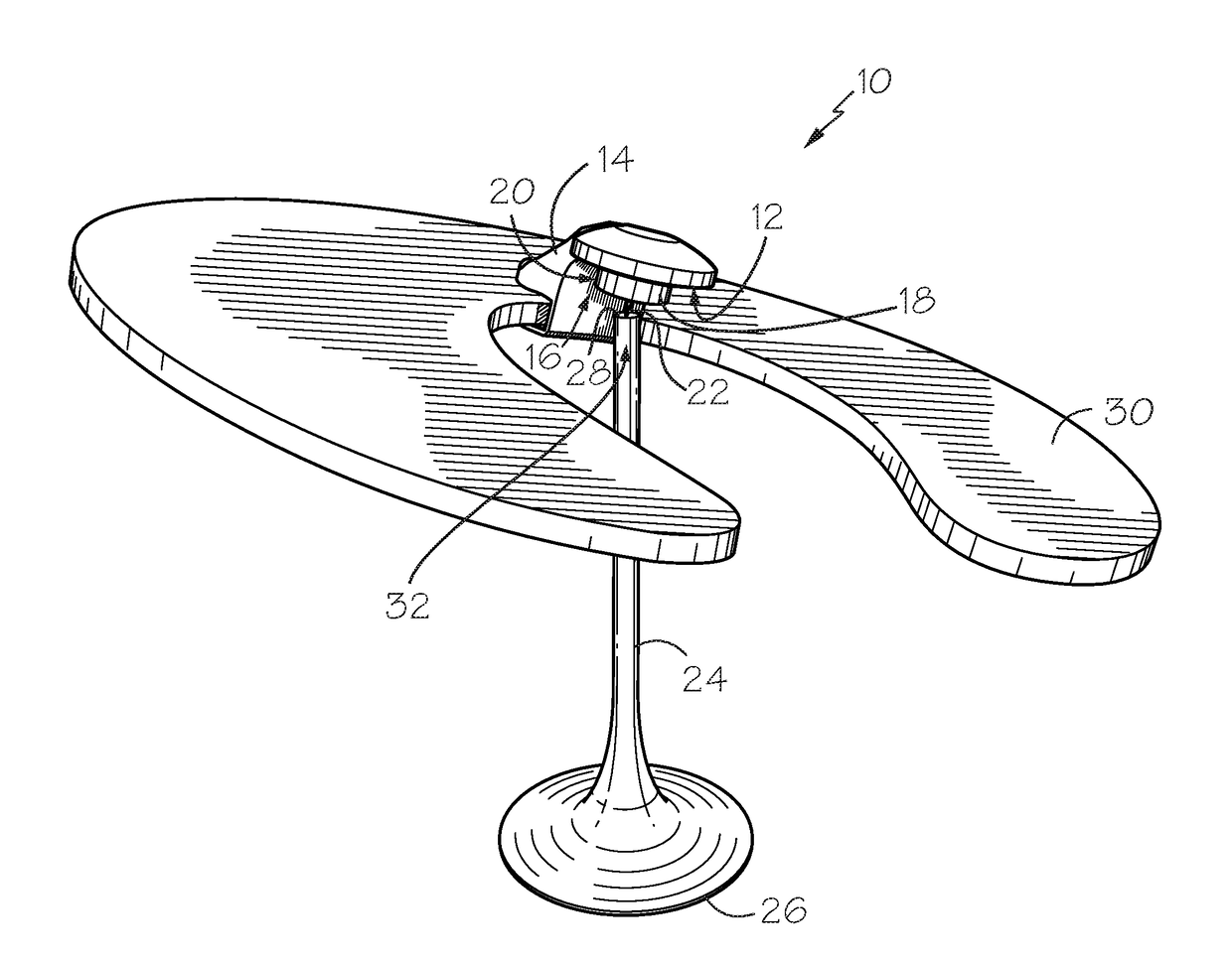
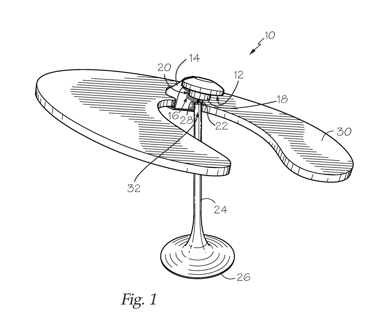
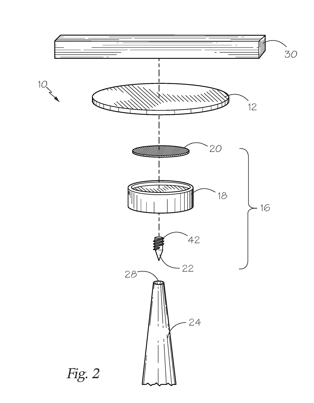
[0028]In a first embodiment, a method of utilizing a balancing device 10 includes a user selecting an object 30 to be balanced. Objects 30 may include one of a number of articles, including—but not limited to—a shaped flat sheet, dish, or even a bottle. Once selected, a user may then affix the ferrous metal plate 12 to the object 30 so the ferrous metal plate 12 is disposed near a point vertically in line with the object's center of gravity 32. For example, if a user selected a U-shaped board 30—as in FIG. 1—the user may clamp 14 the ferrous metal plate 12 to the board 30 so that the plate 12 is located between the legs and base of the board 30, at a point corresponding to the center of gravity 32 of the board 30.

[0029]Once the ferrous metal plate 12 is affixed to the object 30, the user may then attach the balance member 16, through its magnet 20, to a point on the surface of the ferrous metal plate 12. Upon attaching the balance member 16, the user may then pla...


PUM


Abstract

A balancing device which includes a plate which can be affixed to an object to be balanced, a balance member to be removably affixed to the plate, a support, and both the balance member and support having each one of a pointed spike and concave depression which receives the pointed spike. A user affixes the plate to an object to be balanced and attaches the balance member to the plate. Thereafter, a user places the object on top of the support resting on a surface so that the pointed spike is inserted into the concave depression. The object balances upon the support at an angle which can be adjusted by moving where the balance member is attached on the metal plate.

Description

CROSS-REFERENCE TO RELATED APPLICATION[0001]This application claims the benefit of U.S. Provisional Application No. 62 / 456,265, entitled ADJUSTABLE PIVOT POINT ASSEMBLY, filed on Feb. 8, 2017 which is hereby incorporated by reference in its entirety.BACKGROUND OF THE INVENTION[0002]This invention relates to balancing devices of the type which affix at or near an object's center of gravity and which naturally return an object to a balanced angular equilibrium determined by where on the object the device is affixed, in relation to the center of gravity. In particular, the present invention relates to balancing devices capable of achieving a desired angular orientation of an object without rotating such device or adding, moving, or adjusting a counterweight and which can still allow the object to freely rotate about a point.[0003]The ability to balance items about a point, like a tip is known to and particularly useful amongst toys, games, tops, and other novelty devices. However, many...

Claims


Application Information

Patent Timeline
Patent Type & Authority Applications(United States)
IPC IPC(8): A63H33/26A63H1/00A63F9/34
CPCA63H33/26A63F9/34A63H1/00A63F9/00A63F9/26A63F11/0011A63F2009/0013A63F2011/0016A63F2250/024A63F3/00895A63H33/00A63H15/04
Inventor GAMERO, LUIS GERARDO MACHADO
Owner MACHADO GAMERO LUIS GERARDO
Why Eureka
Try Eureka