Reduction tool

Active Publication Date: 2018-08-30
OSTEOMED
View PDF4 Cites 6 Cited by
  • Summary
  • Abstract
  • Description
  • Claims
  • Application Information

AI Technical Summary

Benefits of technology

The present patent describes systems, methods, tools, and screws for reducing bone fractures. The system includes a screw, a driver, a sleeve, and a locking mechanism. The screw has two threaded portions and a non-threaded portion. The sleeve has a longitudinal bore for inserting the driver and a retaining sleeve for applying a compressive force to the bone. The locking mechanism can lock or unlock the sleeve from the driver. The screw has a groove for attaching a retaining sleeve, which can be easily coupled to the screw using a snap fit or compression fit. The technical effects of the invention include improved bone compression and reduced fracture reduction time.

Problems solved by technology

However, it is not always easy to achieve a desired amount of compression during fixation of bone fragments.
However, this technique is not always desirable because the head of the screw protrudes from the bone and may cause discomfort to, or damage, tissues surrounding the bone fracture.
Using headless screws overcomes the drawbacks associated with headed screws, but presents other challenges with respect to achieving the desired amount of compression.
For example, it may be difficult to maintain the appropriate amount of compression during reduction of a bone fracture using headless screws (e.g., because there is no head on the screw to apply a compressive force to the bone fragments and draw the bone fragments together).

Method used


Image

  • Reduction tool
  • Reduction tool
  • Reduction tool

Examples


Embodiment Construction

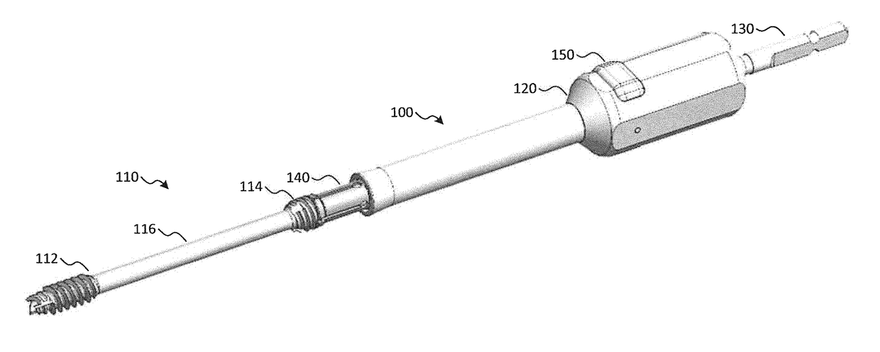
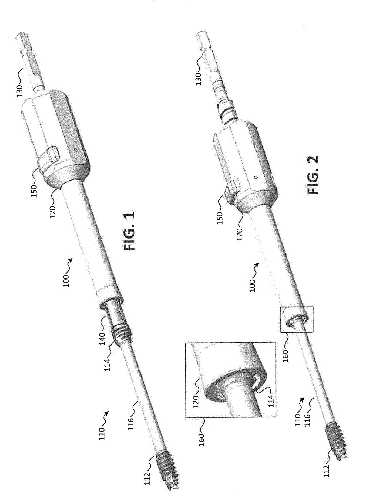
[0028]Referring to FIGS. 1-4, various diagrams illustrating aspects of a system for reducing a bone fracture in accordance with embodiments are shown as a system 100. In embodiments, the system 100 may be used to reduce a fracture of a bone. Additionally, the system 100 may enable compression to be maintained during insertion of a screw into the bone. In embodiments, the screw may be a headless screw.

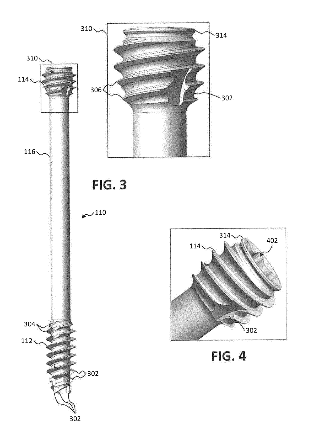
[0029]As shown in FIG. 1, the system 100 for providing reduction of a bone fracture may include a screw 110 and a reduction tool that includes a driver 130, a sleeve 120, a retaining sleeve 140, and a locking mechanism 150. The screw 110 may include a first threaded portion 112, a second threaded portion 114, and a non-threaded portion 116. In some embodiments, the screw 110 may be a cannulated screw. In other embodiments, the screw 110 may not be a cannulated screw. As shown in FIGS. 3 and 4, the first threaded portion 112 may correspond to a first end (e.g., a tip or lead portion) of ...


PUM


Abstract

Systems, tools, and screws for reducing a bone fracture are disclosed. In embodiments, the system comprises: a screw, a driver, a sleeve comprising a longitudinal bore configured to enable insertion of the driver through the sleeve, a locking mechanism configurable into a first state that locks the sleeve to the driver and a second state that unlocks the sleeve from the driver, and a retaining sleeve coupled to a first end of the driver and configured to couple to the screw. In the first state, the sleeve applies a compressive force while distal threads of the screw are driven into the bone while retaining proximal threads of the screw in the sleeve. After a desired compression is achieved, the locking mechanism is configured to the second state, allowing the proximal threads of the screw to be driven into the bone while maintaining application of the compressive force to the bone.

Description

TECHNICAL FIELD[0001]The present application generally relates to systems, methods, and tools for reducing a bone fracture, and more particularly to systems, methods, and tools for providing improved compression during reduction of a bone fracture.BACKGROUND[0002]A bone fracture may result in two fragments or sections of bone becoming separated from one another, and screws may be used to fixate the bone fragments in proper alignment while the bone fragments heal. As the screws are driven into the bone, the fragments or sections may be drawn together, creating compression of the bone fragments, which may promote faster healing of the bone. However, it is not always easy to achieve a desired amount of compression during fixation of bone fragments. One technique for providing fixation and compression of these types of fractures involves driving one or more headed screws through the bone fragments. As the screw is driven into the bone, the head of the screw applies a force that draws th...

Claims


Application Information

Patent Timeline
IPC IPC(8): A61B17/86A61B17/88
CPCA61B17/8645A61B2017/681A61B17/8891A61B17/862A61B17/863
Inventor MAREK, MATTHEW GEOFFREYMOCANU, VIORELLITKE, RONALDSHORE, SPENCERREED, SCOTT
Owner OSTEOMED
Why Eureka
Try Eureka