Eureka AIR delivers breakthrough ideas for toughest innovation challenges, trusted by R&D personnel around the world.

Cutting tool

Active Publication Date: 2018-09-13
TAEGUTEC
View PDF2 Cites 6 Cited by
  • Summary
  • Abstract
  • Description
  • Claims
  • Application Information

AI Technical Summary

Benefits of technology

The cutting tool in this patent has improved its ability to cut and is firmer and more stable. This means that it can better hold its shape and can be used for more cutting tasks.

Problems solved by technology

However, when the point angle of the cutting tool is reduced, the rigidity of its cutting portion may be undesirably lowered, ultimately resulting in an increased torque of the cutting tool during the cutting process.
In addition, when the cutting tool having a small point angle passes through a to-be-cut material, the size of a burr generated in the perforation process may increase.

Method used


Image

  • Cutting tool
  • Cutting tool
  • Cutting tool

Examples


Embodiment Construction

[0026]Advantages and features of the present invention and methods of accomplishing the same may be understood more readily by reference to the following detailed description of preferred embodiments and the accompanying drawings. The present invention may, however, be embodied in many different forms and should not be construed as being limited to the embodiments set forth herein. Rather, these embodiments are provided so that this disclosure will be thorough and complete and will fully convey the concept of the invention to those skilled in the art, and the present invention will only be defined by the appended claims. In the drawings, the size and relative sizes of layers and regions may be exaggerated for clarity.

[0027]The terminology used herein is for the purpose of describing particular embodiments only and is not intended to be limiting of the invention. As used herein, the singular forms are intended to include the plural forms as well, unless the context clearly indicates ...


PUM


Abstract

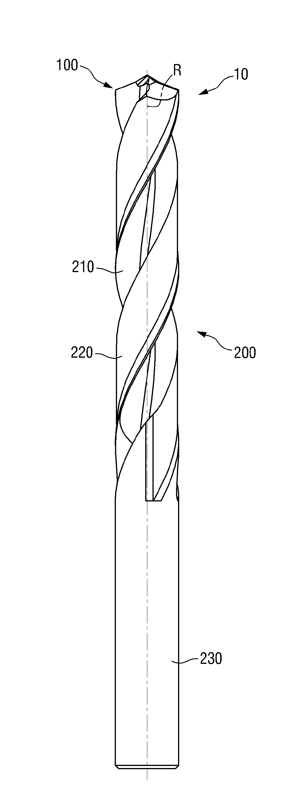
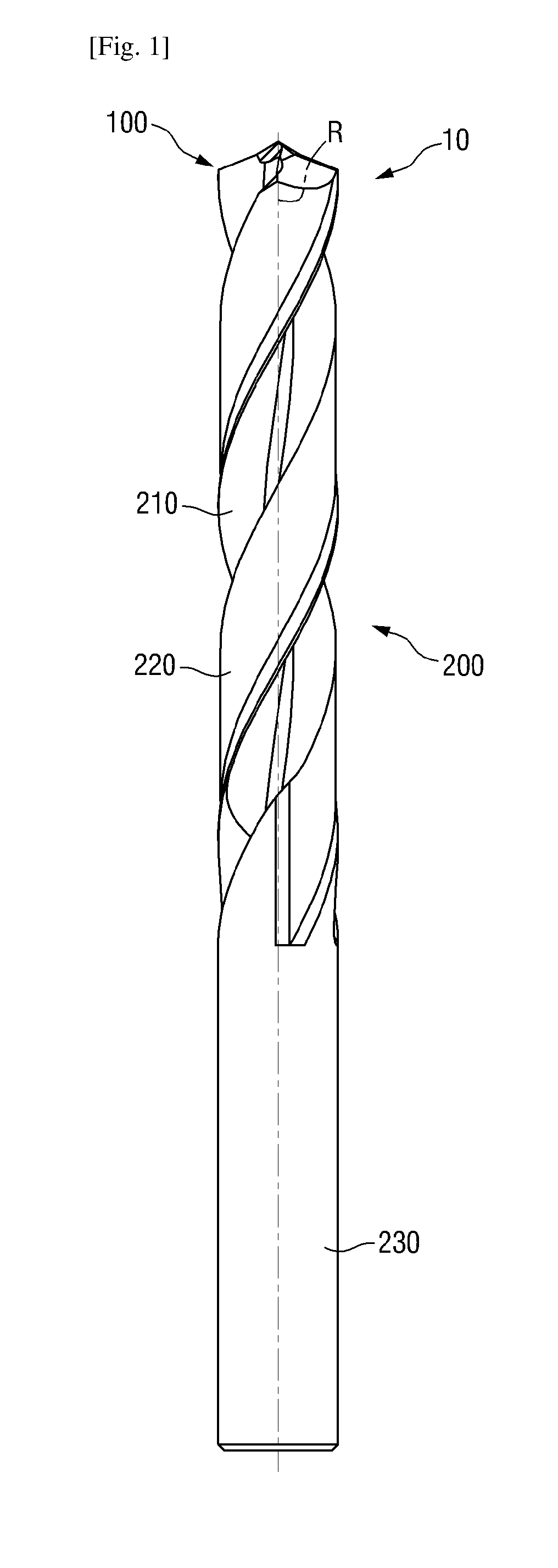
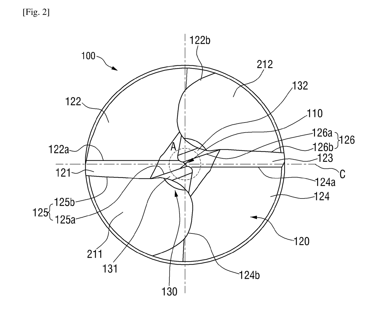
A drill includes a drill body rotatable about a drill axis, and a cutting portion. The cutting portion includes a first grinding face having first and second chisel edges defining an angle therebetween, and a second grinding face having third and fourth chisel edges defining an angle therebetween, the second grinding face being point-symmetrical with the first grinding face. A first relief face associated with a first cutting edge extends from the first and fourth chisel edges and a second relief face associated with a second cutting edge extends from the second and third chisel edges. A first intersection line is formed where the first and second relief faces meet; a second intersection line is formed where the third and fourth relief faces meet. The first and second intersection lines are spaced apart from an imaginary center line passing through the rotational axis and the first and third relief faces.

Description

TECHNICAL FIELD[0001]The present invention relates to a cutting tool, and more particularly, to a cutting tool having an improved centripetal property and rigidity.BACKGROUND ART[0002]With the recent demand for precision machining in the field of cutting processes, development of high-performance cutting tools is urgently needed to perform elaborate perforation without additionally performing a subsequent process, such as a finishing operation.[0003]In the cutting process, a centripetal property of a cutting tool can be improved by a high degree of precision in a perforation process, leading to improvement in the precision in view of hole size and shape. The centripetal property of the cutting tool can be improved by reducing a point angle.[0004]However, when the point angle of the cutting tool is reduced, the rigidity of its cutting portion may be undesirably lowered, ultimately resulting in an increased torque of the cutting tool during the cutting process.[0005]In addition, when ...

Claims


Application Information

Patent Timeline
IPC IPC(8): B23B51/02
CPCB23B51/02B23B2251/04B23B2251/14B23B2251/18B23B2251/40Y10T408/9097Y10T408/9065
Inventor PARK, JUNG HOON
Owner TAEGUTEC
Why Eureka
Eureka Blog
Learn More