Fenestrated spinal implant

a spinal implant and implant technology, applied in the field of surgical implants, can solve the problems of not being able to effectively deposit bone or other materials such as bone cement, bone cement, or some other type of bone biologic, and not being able to meet one or more unsolved needs recognized by the inventor

Inactive Publication Date: 2018-10-11
QUANDARY MEDICAL
View PDF11 Cites 1 Cited by
  • Summary
  • Abstract
  • Description
  • Claims
  • Application Information

AI Technical Summary

Problems solved by technology

These solutions, however, have failed to meet one or more unsolved needs recognized by the inventor because of still-remaining challenges.
Moreover, previous implants intended to accomplish pre-sacral interbody fusion do not allow bone to grow into and th

Method used


Image

  • Fenestrated spinal implant
  • Fenestrated spinal implant
  • Fenestrated spinal implant

Examples


Embodiment Construction

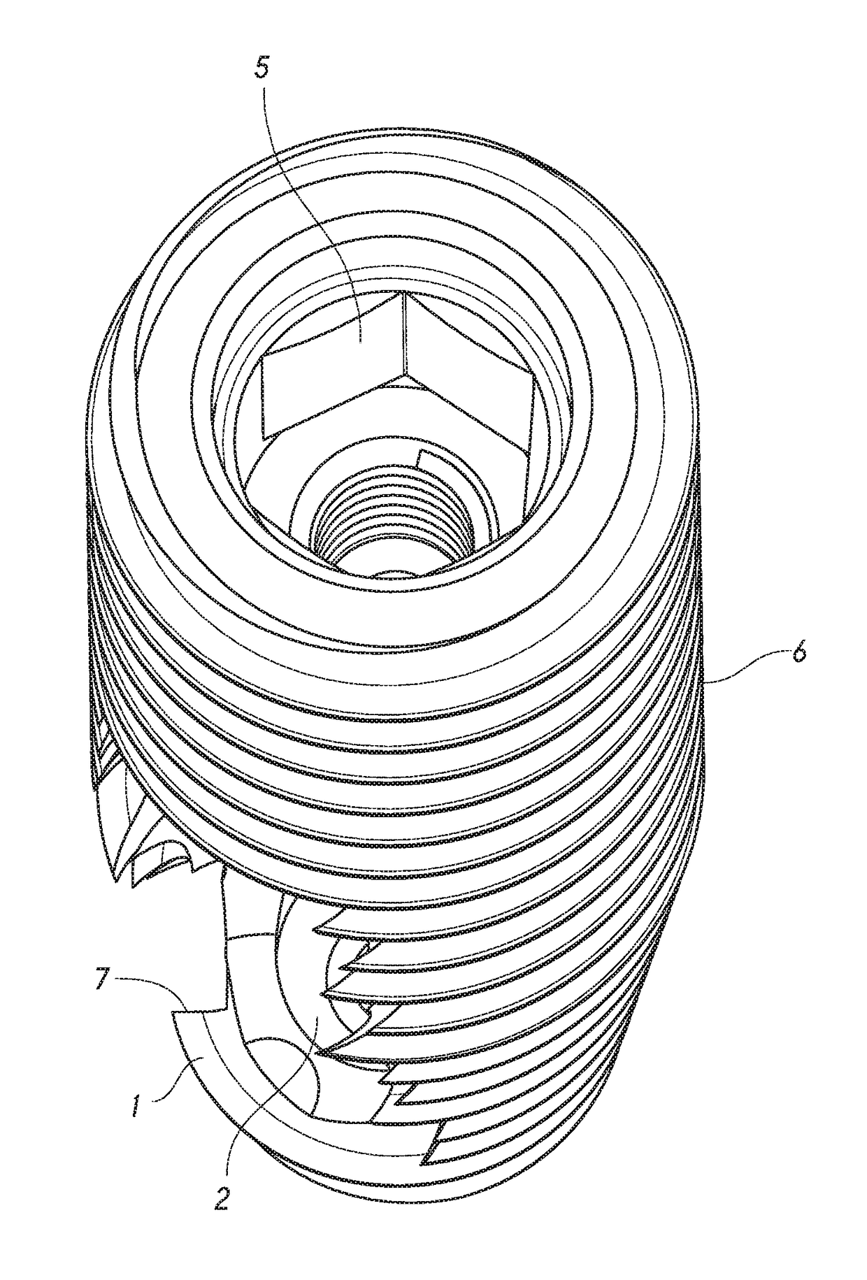
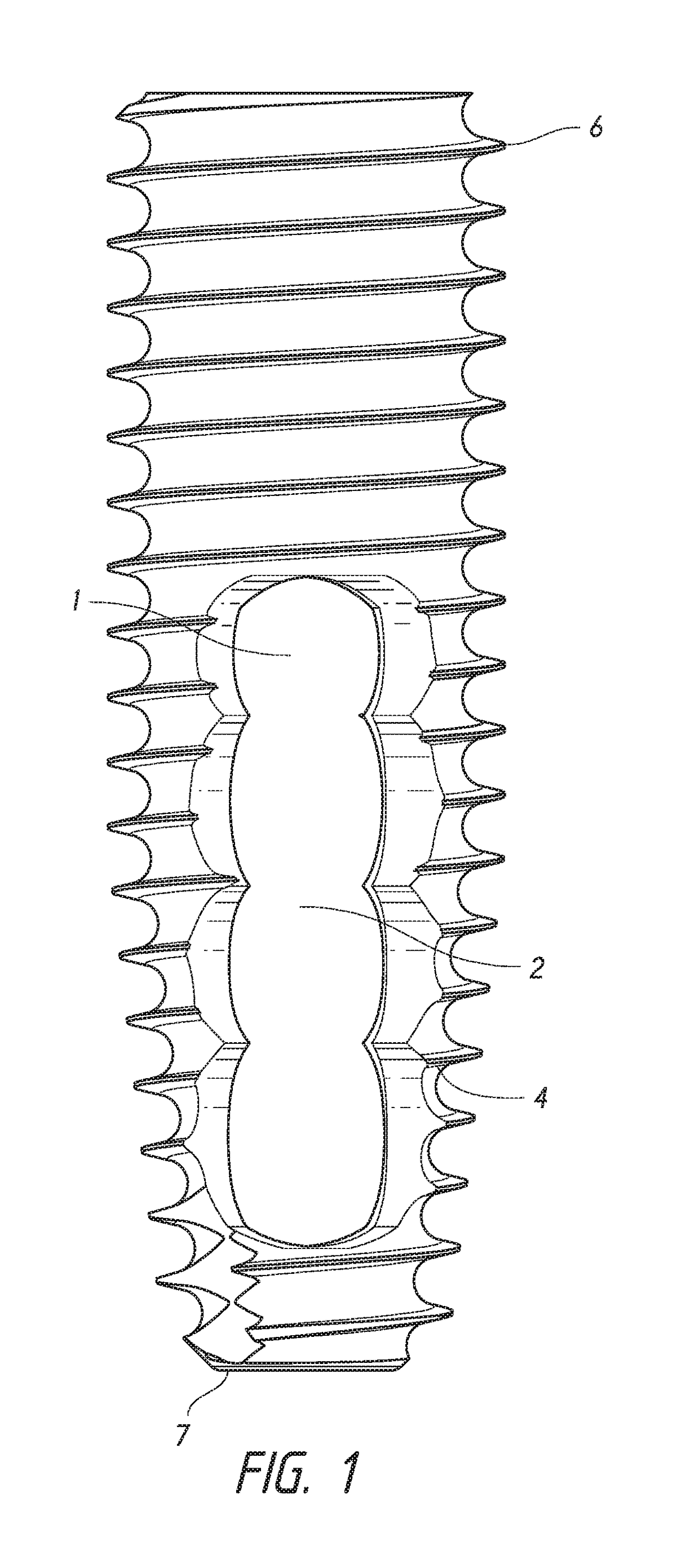
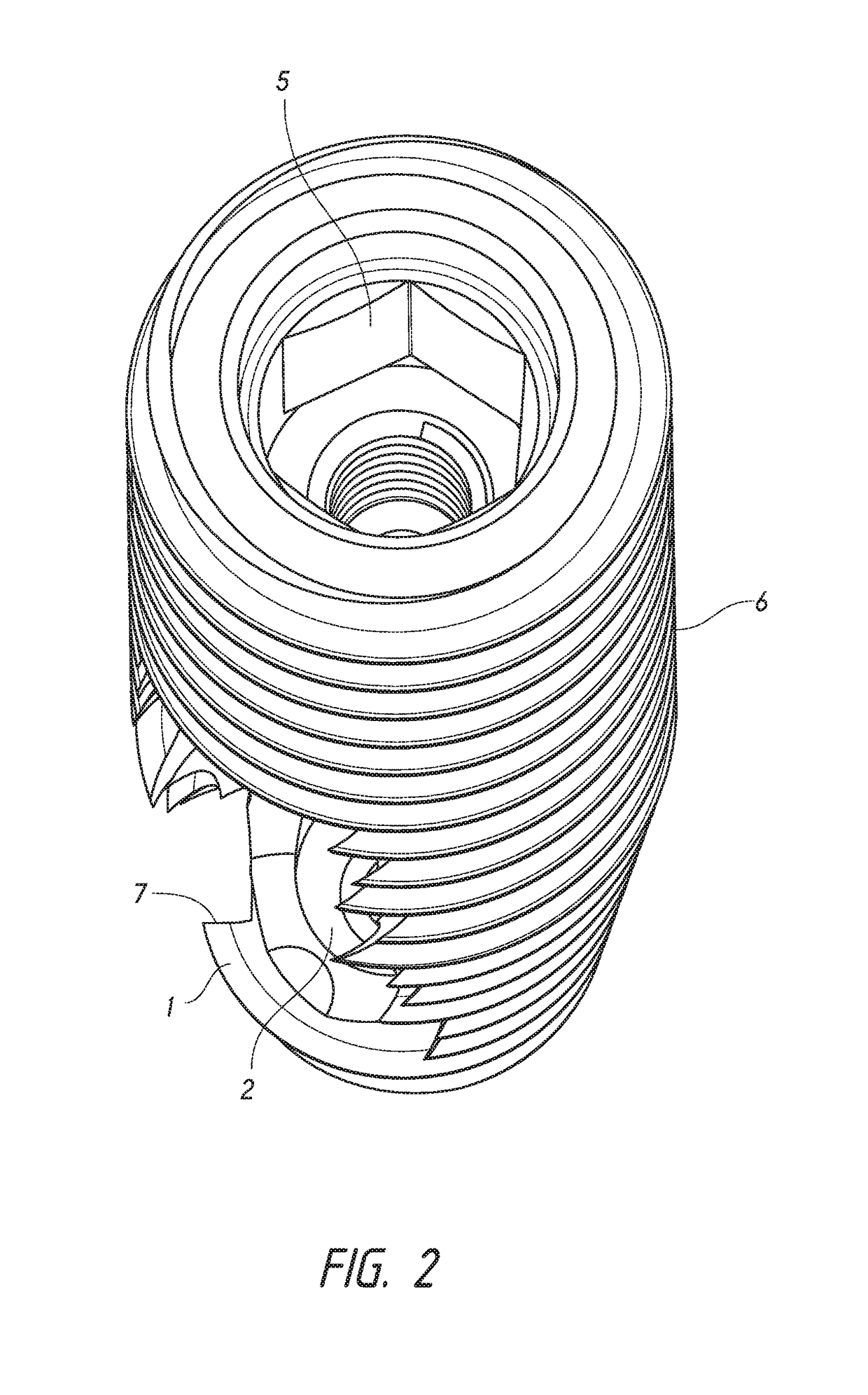
[0027]The preferred embodiment of the present invention is described as a fenestrated non-distracting implant. In the preferred mode of use, the implant, in the preferred embodiment more precisely described as a fenestrated non-distracting implant, is utilized in association with fusion of the L5 and S1 vertebral bodies. Generally, the inventors intend for the implant to function via advancing through the sacral vertebral body by a method commonly described as “the pre-sacral approach” as known in the prior art, and as more specifically described in U.S. Pat. No. 6,575,979 which is hereby incorporated by reference in its entirety, through the L5-S1 interbody space, and into the L5 vertebral body. In the preferred method of use, during passage through the S1 vertebral body, fenestrations within the implant are configured to interact with the sacrum as the implant advances and collect bone tissue from the sacrum into the fenestrations. The implant, in the preferred embodiment may also...


PUM


Abstract

The present invention relates to an implant, and more precisely in the preferred embodiment, a fenestrated non-distracting rod for use in association with spinal surgery. The implant is to be placed via the pre-sacral approach in an embodiment of the invention. The fenestrations incorporated within the preferred embodiment are configured to collect bone during transit through the sacrum, and then optionally configured to contact and/or deposit bone collected into the L5-S1 disc space area.

Description

CROSS-REFERENCES TO RELATED APPLICATIONS[0001]This application claims the benefit of provisional application Ser. No. 62 / 483,974, filed on Apr. 11, 2017, incorporated herein by reference.FIELD OF THE INVENTION[0002]The present invention relates to surgical implants, and more specifically, surgical implants utilized in association with spine surgery.BACKGROUND OF THE INVENTION[0003]The present inventors have recognized the problem of creating a bone bridge between the L5 and S1 vertebral bodies during pre-sacral interbody fusion. Other solutions for the problem of creating fusion between the L5 and S1 vertebral bodies during pre-sacral interbody fusion exist in the prior art. These solutions, however, have failed to meet one or more unsolved needs recognized by the inventor because of still-remaining challenges. Moreover, previous implants intended to accomplish pre-sacral interbody fusion do not allow bone to grow into and through the implant. In addition, the previous implants do n...

Claims


Application Information

Patent Timeline
IPC IPC(8): A61F2/44A61F2/30A61F2/28
CPCA61F2/4455A61F2/442A61F2/30771A61F2/28A61F2002/4475A61F2002/30774A61F2/446A61F2002/30772A61F2002/30777A61F2002/30784A61F2002/3085A61F2002/30873A61F2002/30851A61F2002/30593
Inventor ARTHURS, BRANDONNOBLE, SCOTTARCE, RYANLAPIERRE, LEIGHTONSCHELL, JEFFREY
Owner QUANDARY MEDICAL
Why Eureka
Try Eureka