Induction heating coil

a technology of induction heating coil and coil section, which is applied in the direction of induction current source, manufacturing tools, coil arrangement, etc., can solve the problems of difficulty in making the coil section from a single member, difficulty in reducing the lifetime of the induction heating coil, and insufficient skill, so as to reduce the imbalance of heat stress, prolong the lifetime of the induction heating coil, and improve the effect of heat dissipation

Inactive Publication Date: 2018-11-08
KOYO THERMO SYST CO LTD
View PDF3 Cites 2 Cited by
  • Summary
  • Abstract
  • Description
  • Claims
  • Application Information

AI Technical Summary

Benefits of technology

[0008]Furthermore, when the plurality of members constituting the coil section are brazed to each other, and when the coil section and the power supply section are brazed to each other, the brazing temperature is high, and thus heat strain inevitably occurs between the plurality of members constituting the coil section and between the coil section and the power supply section. Accordingly, a special jig is needed for lowering such heat strain, when brazing is performed on the coil section and the power supply section. Design of this jig as well requires a high level intuition and experience for lowering heat strain in the coil section and the power supply section.
[0044]Accordingly, the lifetime of the induction heating coil can further be extended. Furthermore, the coil section and the power supply section are formed in one piece of unified structure from the same electrically-conductive metal material. Therefore, as compared with the conventional coil section and power supply section that are formed by brazing to combine a plurality of pieces which are made from different kind of metal materials respectively , variation in electrical resistivity per unit volume in the entire region of the coil section and the power supply section is small. Furthermore, variation in electrical resistivity (Ω⋅m) per unit volume (1 mm3) in the entire region of the coil section and the power supply section is 5% or less. Therefore, there is not likely to be a difference in the variation in expansion and shrinkage amount of the coil section and the power supply section in case of the expansion or shrinkage caused on the sections under thermally-stressed conditions. Accordingly, fatigue failure in the coil section and the power supply section can be prevented, and the extension of the lifetime of the coil section and the power supply section can further extend the lifetime of the induction heating coil.

Problems solved by technology

Accordingly, the coil section has a complicated shape, and it is difficult to make the coil section from a single member.
In order to perform a brazing operation with accuracy, however, proficient skill is needed.
As a result, it is difficult to keep the brazing accuracy constant for each induction heating coil, and also difficult to make the induction heating coils in mass production with them formed in same (uniform) dimensions or shapes each other.
Furthermore, when the plurality of members constituting the coil section are brazed to each other, and when the coil section and the power supply section are brazed to each other, the brazing temperature is high, and thus heat strain inevitably occurs between the plurality of members constituting the coil section and between the coil section and the power supply section.
Furthermore, when brazing is performed on the coil section and the power supply section, it takes not only time for setting the above-described jig but also a lot of troublesome works to prepare the jig, resulting in a lowered efficiency of producing the induction heating coils.
Moreover, processes of brazing and machining the induction heating coil are low in their flexibility to set their conditions.
This will reduce the scope of conditions in setting the shape of the induction heating coil for achieving the heat treatment most appropriate for a treatment target subjected to the treatment.

Method used


Image

  • Induction heating coil
  • Induction heating coil
  • Induction heating coil

Examples


first embodiment

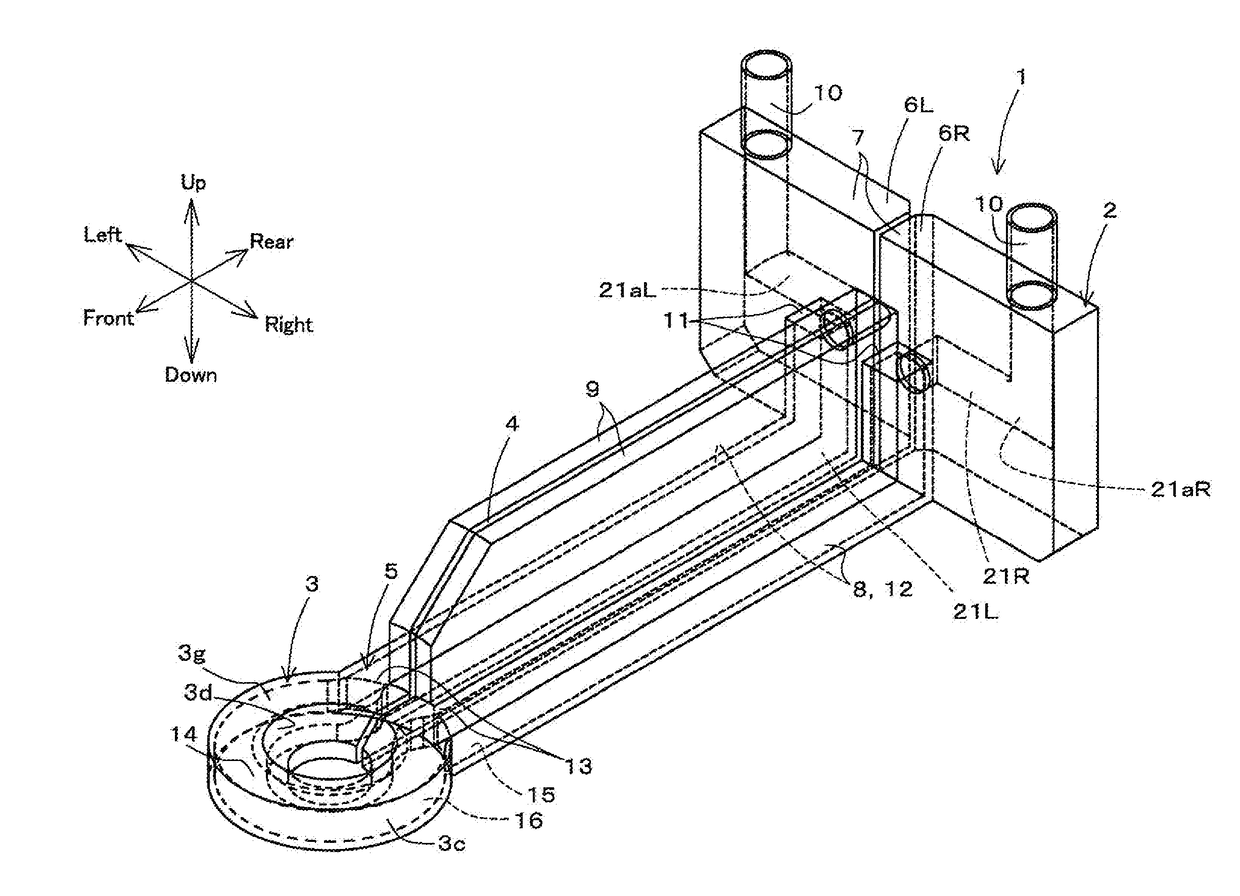
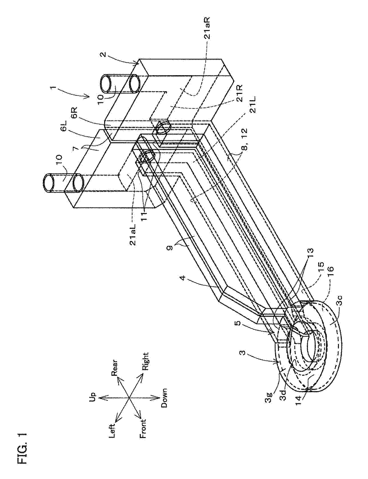
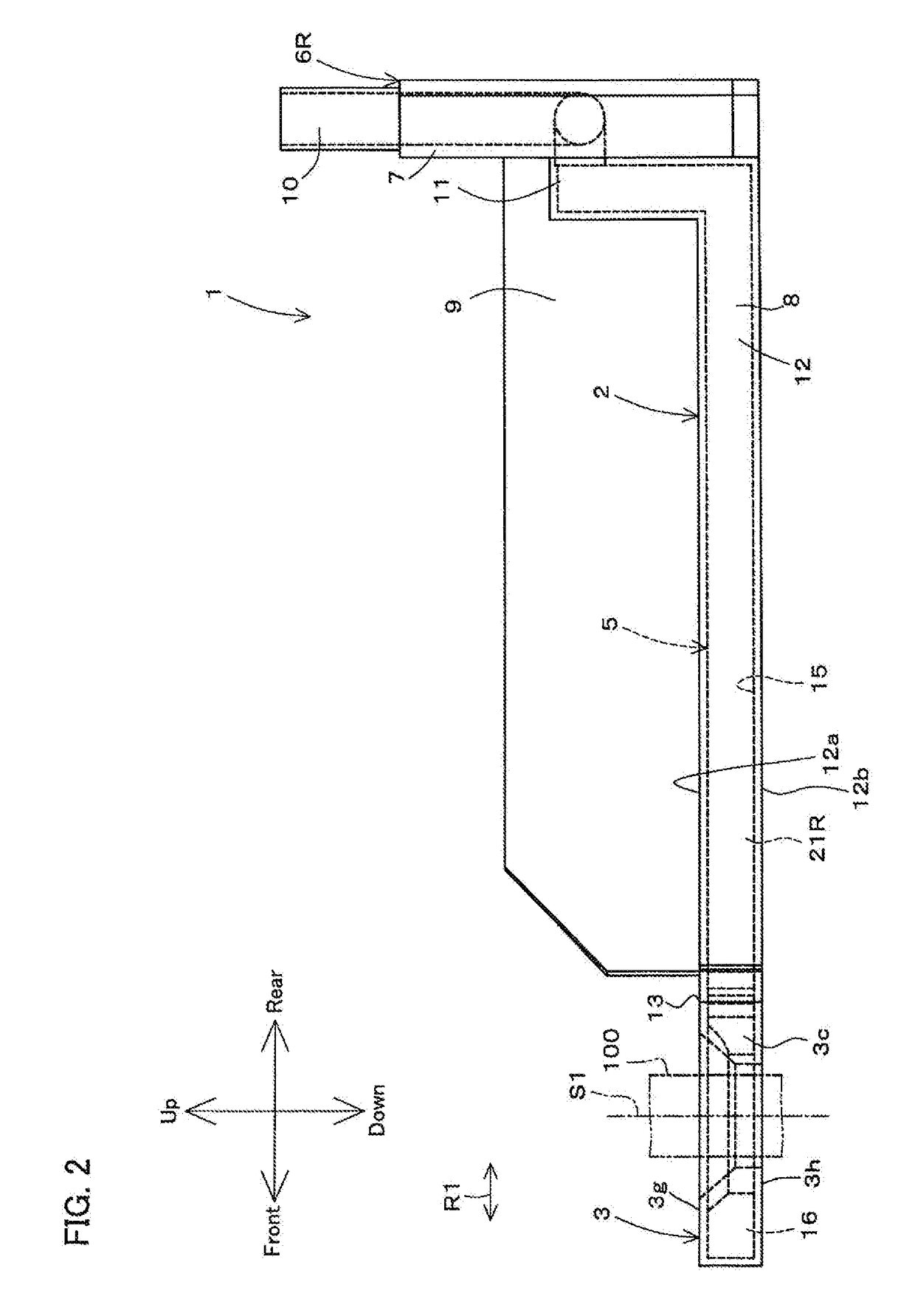
[0071]FIG. 1 is a perspective view of an induction heating coil 1 according to a first embodiment of the present invention. FIG. 2 is a side view of the induction heating coil 1. FIG. 3 is a plan view of the induction heating coil 1. FIG. 4 is a cross-sectional view of the state in which the periphery of a coil section 3 of the induction heating coil 1 is viewed in a plan view. FIG. 5 is a cross-sectional view of the state in which the periphery of the coil section 3 is viewed in a side view. FIG. 6 is an enlarged perspective view of the periphery of the coil section 3 of the induction heating coil 1.

[0072]Note that in the following, “up and down”, “front and rear”, and “right and left” respectively refer to “up and down”, “front and rear”, and “right and left” when a viewer views the induction heating coil 1 in the state of facing the front surface of the induction heating coil 1.

[0073]Referring to FIGS. 1 to 3, the induction heating coil 1 is used for performing heat treatment, su...


PUM

PropertyMeasurementUnit
currentaaaaaaaaaa
electrical resistivityaaaaaaaaaa
poweraaaaaaaaaa

Abstract

An induction heating coil includes a coil section configured to heat a treatment target by induction, a power supply section configured to supply power to the coil section, and a cooling medium passage that is arranged in the power supply section and the coil section, and is configured to supply a cooling medium to the coil section. The coil section, the power supply section, and the cooling medium passage are formed using a metal additive fabrication method.

Description

CROSS-REFERENCE TO RELATED APPLICATIONS[0001]This application is a divisional of U.S. patent application Ser. No. 14 / 702,510, which claims priority to Japanese Patent Application No. 2014-98906. The entire disclosures of U.S. patent application Ser. No. 14 / 702,510 and Japanese Patent Application No. 2014-98906 are hereby incorporated herein by reference.BACKGROUND OF THE INVENTION1. Field of the Invention[0002]The present invention relates to an induction heating coil.2. Description of Related Art[0003]An induction heating coil may be used in order to, for example, subject metal machine parts such as a shaft to a heat treatment by high frequency induction heating (see JP 2013-136819A, for example). An induction heating coil disclosed in JP 2013-136819A includes a circular ring-shaped coil section which is constituted to surround a shaft serving as a treatment target. A large current is supplied to the coil section to operate it to carry out the induction heating.[0004]This high elec...

Claims


Application Information

Patent Timeline
Patent Type & Authority Applications(United States)
IPC IPC(8): B23K26/34H05B6/42H05B6/04
CPCB23K26/34H05B6/42H05B6/04B33Y10/00B33Y80/00B23K26/342Y02P10/25B23K26/346
Inventor YAMAMOTO, RYOSUKENAKATA, AYAKAFUJIYAMA, NORIHIDE
Owner KOYO THERMO SYST CO LTD
Why Eureka
Try Eureka