Method of manufacturing differential device

a technology of differential devices and manufacturing methods, applied in the direction of transportation and packaging, other domestic objects, gearing, etc., can solve the problems of increasing the number of welding steps, reducing manufacturing costs, and reducing welding efficiency, so as to achieve efficient welding

Active Publication Date: 2015-07-02
MUSA PRECISION IND CO LTD
View PDF6 Cites 4 Cited by
  • Summary
  • Abstract
  • Description
  • Claims
  • Application Information

AI Technical Summary

Benefits of technology

[0006]The present invention has been accomplished in view of the above-described circumstances, and an object of the present invention is to provide a method of manufacturing a differential device in which a press-fit portion between a ...

Problems solved by technology

Such a structure is effective in reducing welding distortion of the ring gear, but increases the number of welding steps to make manufacturing cost reduction difficult...

Method used


Image

  • Method of manufacturing differential device
  • Method of manufacturing differential device
  • Method of manufacturing differential device

Examples


Embodiment Construction

[0018]Hereinafter, an embodiment of the present invention will be described based on the accompanying drawings.

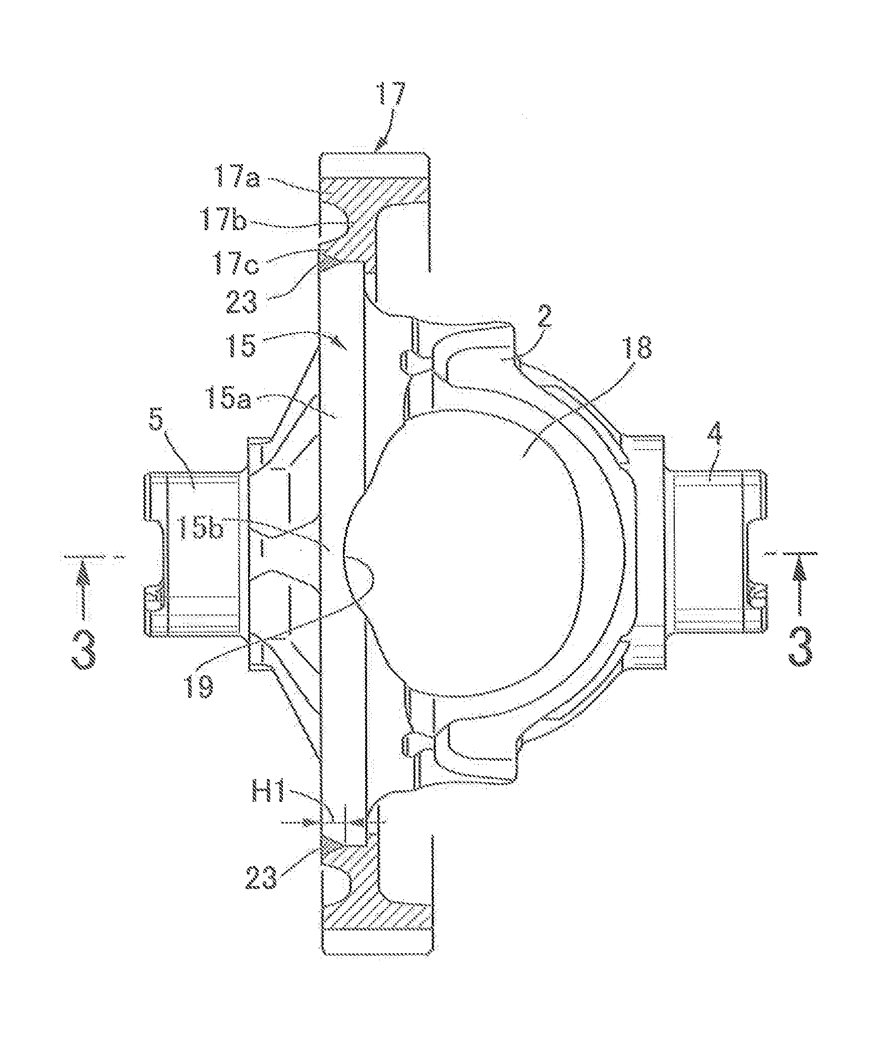
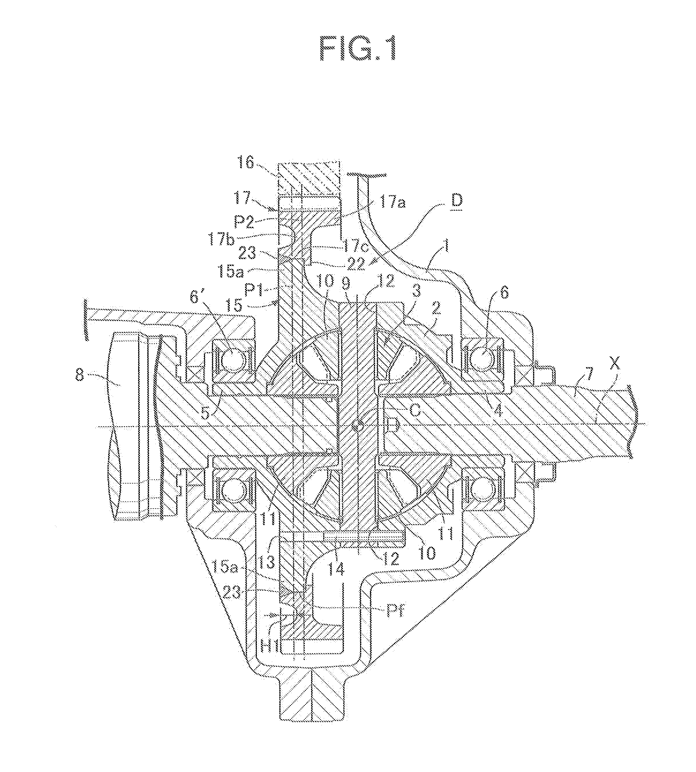
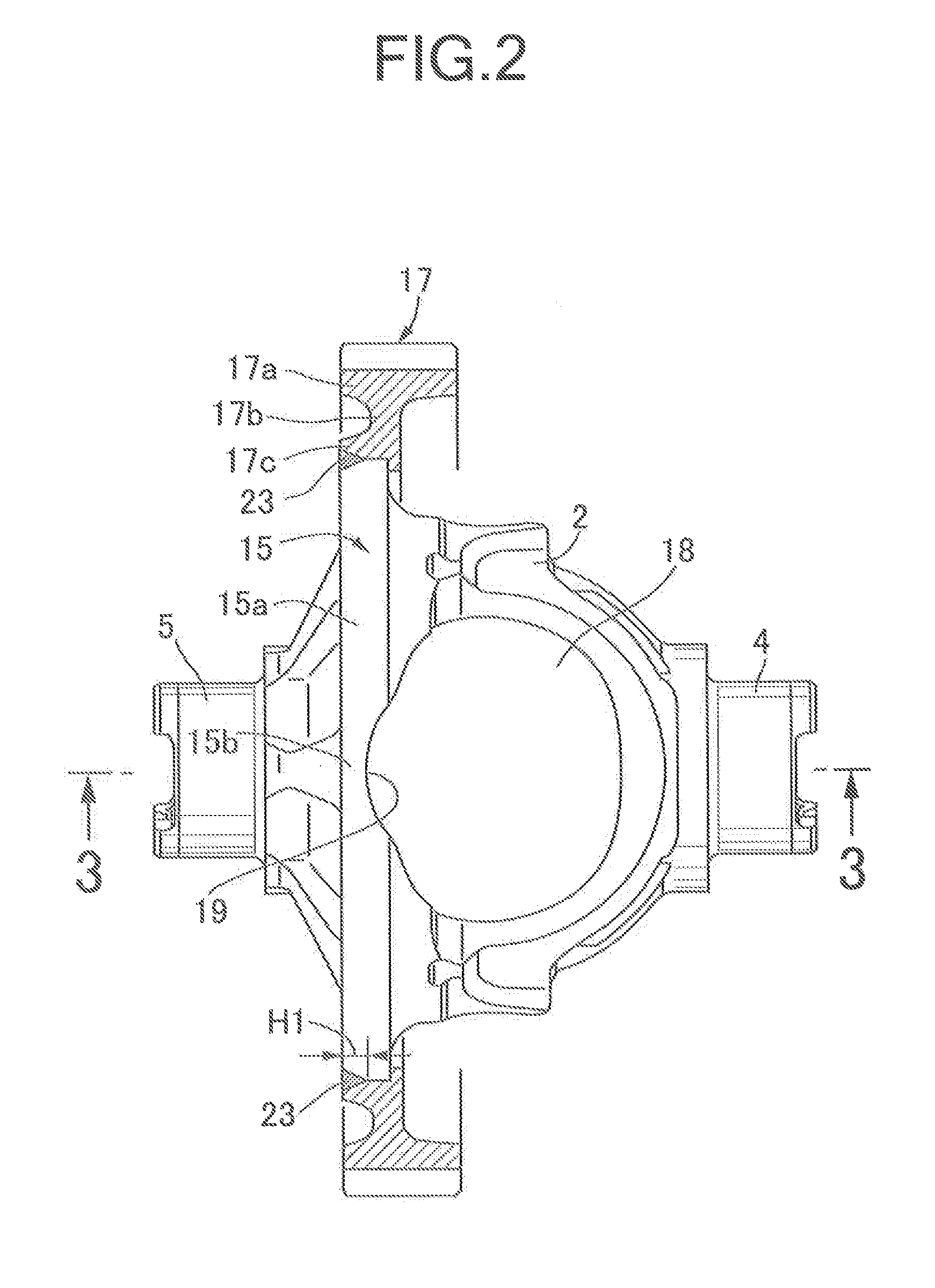
[0019]In FIG. 1, a differential device D is housed in a transmission case 1 of a vehicle. This differential device D includes a differential case 2 and a differential mechanism 3 housed in this differential case 2. On a right side portion and a left side portion of the differential case 2, a first bearing boss 4 and a second bearing boss 5 aligned on the same axis X are formed integrally therewith. These first and second bearing bosses 4, 5 are supported by the transmission case 1 via bearings 6 and 6′, and support right and left axles 7, 8.

[0020]The differential mechanism 3 includes a pinion shaft 9 held by the differential case 2 to be orthogonal to the axis X, a pair of pinion gears 10 supported by the pinion shaft 9, and a pair of side gears 11 spline-connected to inner ends of the axles 7, 8 to mesh with the pinion gears 10. A back face of each gear is rotatably suppor...


PUM

PropertyMeasurementUnit
Depthaaaaaaaaaa

Abstract

In a method of manufacturing a differential device, a hub of a ring gear is press-fitted to a flange from a first bearing boss side, then a press-fit portion between the flange and the ring gear is equally divided into a plurality of divided regions arranged along a peripheral direction, and simultaneously the divided regions are welded. Accordingly, the press-fit portion between the flange and the ring gear can be efficiently welded while welding distortion of the ring gear is eliminated or reduced even in a case where work windows of a differential case cut into a side surface of the flange on the first bearing boss side to form recessed portions.

Description

BACKGROUND OF THE INVENTION[0001]1. Field of the Invention[0002]The present invention relates to a differential device, especially a method of manufacturing the same, which comprises a differential mechanism and a differential case housing the differential mechanism, the differential case including: first and second bearing bosses formed integrally therewith on one side portion and other side portion of the differential case and aligned on a same axis; an annular flange formed integrally therewith on an intermediate portion which is offset from a center of the differential case toward the second bearing boss side; work windows for inserting the differential mechanism, the work windows being provided in portions of a peripheral wall of the differential case which face each other on a diametral line orthogonal to the axis; a ring gear press-fitted to an outer peripheral surface of the flange; and a press-fit portion between the flange and the ring gear being welded on the second beari...

Claims


Application Information

Patent Timeline
IPC IPC(8): F16H48/38
CPCF16H2048/382F16H48/38F16H48/40F16H2048/385Y10T29/49464
Inventor YANASE, YOICHI
Owner MUSA PRECISION IND CO LTD
Why Eureka
Try Eureka