Heat source system

A heat source system and heating system technology, which is applied in the field of welding and manufacturing of electronic devices, can solve problems such as unsatisfactory thermal separation of components, and achieve the effect of improving welding efficiency

Active Publication Date: 2013-09-11
레노보인터내셔널리미티드
View PDF7 Cites 13 Cited by
  • Summary
  • Abstract
  • Description
  • Claims
  • Application Information

AI Technical Summary

Problems solved by technology

However, these devices are not ideal for thermal separation of components
In some extreme cases, the existing technology can only use separate proces

Method used


Image

  • Heat source system
  • Heat source system
  • Heat source system

Examples


Embodiment Construction

[0013] The specific implementation manners of the present invention are described below in conjunction with the accompanying drawings and examples. However, it should be understood that the following descriptions of specific embodiments are only for explaining implementation examples of the present invention, and do not limit the scope of the present invention in any way.

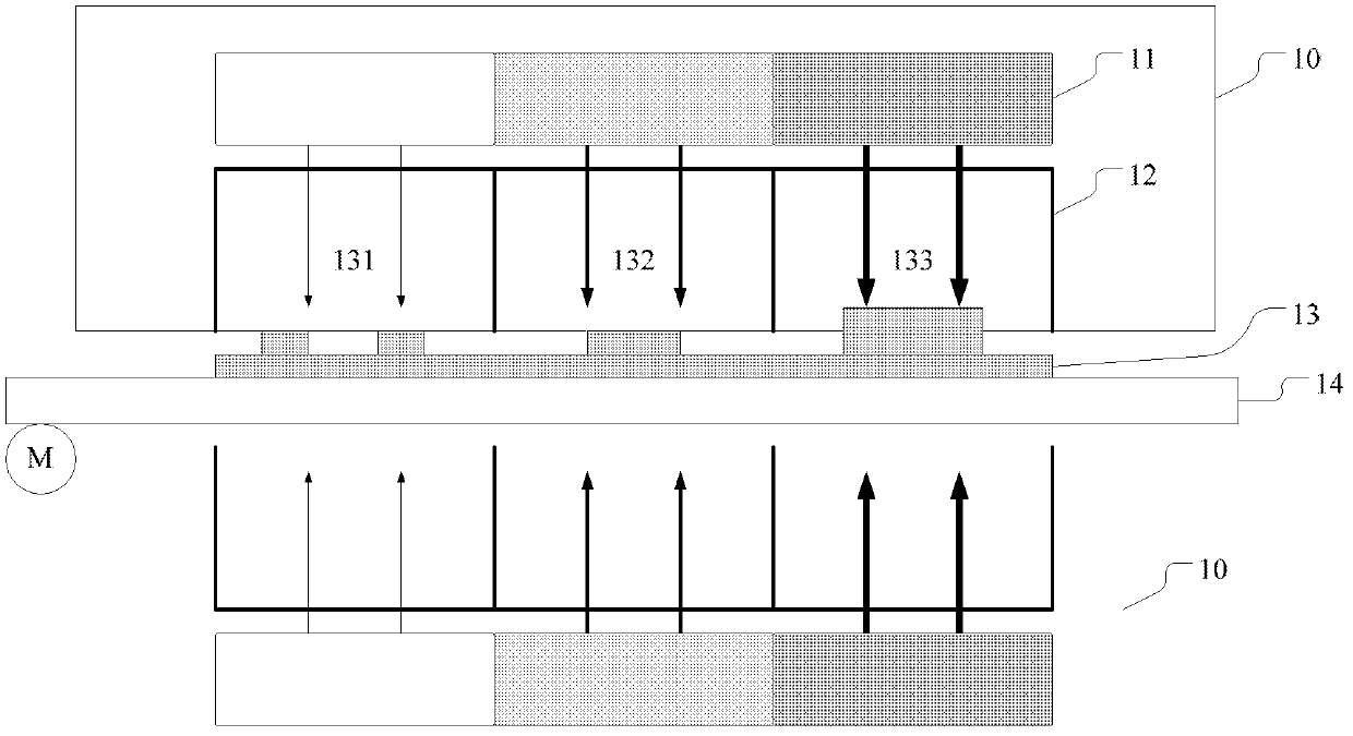
[0014] figure 1 A schematic structure of a heat source system according to an embodiment of the present invention is shown. Such as figure 1 As shown, a heat source system 10 according to an embodiment includes a heating system 11 and a heat distribution system 12 . The heating system 11 is used to provide non-uniform heating gas, such as figure 1 indicated by the middle arrow. Specifically, the thicker arrow on the right shows a more heated, higher temperature gas, and the thinner arrow on the left shows a less heated, lower temperature gas. Correspondingly, the heat distribution system 12 is used to ...


PUM


Abstract

The invention provides a heat source system which comprises a heating system and a heat distribution system, wherein the heating system comprises a gas supply unit and a temperature control unit; the gas supply unit is used for supplying flow gas; the temperature control unit comprises a base plate, and a plurality of through holes are formed in the base plate so as to allow the flow gas to pass; a temperature regulation device is arranged aiming at least a part of the plurality of the through holes, and can regulate the temperature of the flow gas passing the corresponding through holes independently; and the heat distribution system comprises a partition device which divides the heat distribution system into a plurality of areas, so that the flow gas passing the plurality of through holes reaches to-be-heated objects in the plurality of areas. The heat source provided by the embodiment of the invention can provide non-uniform heating as required.

Description

technical field [0001] The invention relates to the field of welding and manufacturing of electronic devices, more specifically, relates to a heat source system that can be used for device welding. Background technique [0002] In the manufacturing process of electronic devices, it is often necessary to solder various components to a pre-arranged circuit board to form a board with specific computing logic. With the continuous miniaturization of PCB boards (printed circuit boards) used in electronic devices, reflow soldering is usually used to achieve soldering of components to circuit boards. In the reflow soldering process, the soldering furnace is used to provide a heating environment to remelt the solder pre-distributed on the pads of the printed board, thereby achieving mechanical and electrical connections between the component terminals or pins and the pads of the printed board. Currently commonly used reflow soldering techniques include far infrared reflow soldering,...

Claims


Application Information

Patent Timeline
IPC IPC(8): B23K3/053B23K3/08H05K3/34
Inventor 张伟锋蒲柯石勇黄小伟甄寿德
Owner 레노보인터내셔널리미티드
Why Eureka
Try Eureka