Detection and control system for container corrugated plate welding track based on laser ranging

A technology of laser distance measurement and control system, applied in general control system, control/adjustment system, control using feedback, etc., can solve problems such as detection accuracy droplet transition form, influence of splash, application method is difficult to master, etc., to achieve Facilitate streamlined operation, improve welding quality and welding efficiency, and reduce labor intensity

Inactive Publication Date: 2009-10-14
SHANDONG UNIV
View PDF0 Cites 38 Cited by
  • Summary
  • Abstract
  • Description
  • Claims
  • Application Information

AI Technical Summary

Problems solved by technology

The contact sensor converts the change of the welding seam into the position change of the guide rod or the guide wheel, and converts it into an electrical signal. Due to its stable performance and low cost, this sensor has been widely used in production. Due to the limitation of tracking accuracy and speed, it has been It is not suitable for high-precision and high-speed welding fields; the arc sensor uses the parameters of the arc itself as the tracking target, and can respond to changes in the weld seam in real time, but the detection accuracy is easily affected by the droplet transfer form and spatter during the welding process, especially for thin plates In the welding of butt joints and lap joints, the application method is difficult to master

Method used


Image

  • Detection and control system for container corrugated plate welding track based on laser ranging
  • Detection and control system for container corrugated plate welding track based on laser ranging
  • Detection and control system for container corrugated plate welding track based on laser ranging

Examples


Embodiment Construction

[0043] The present invention will be further described below in conjunction with the accompanying drawings and embodiments.

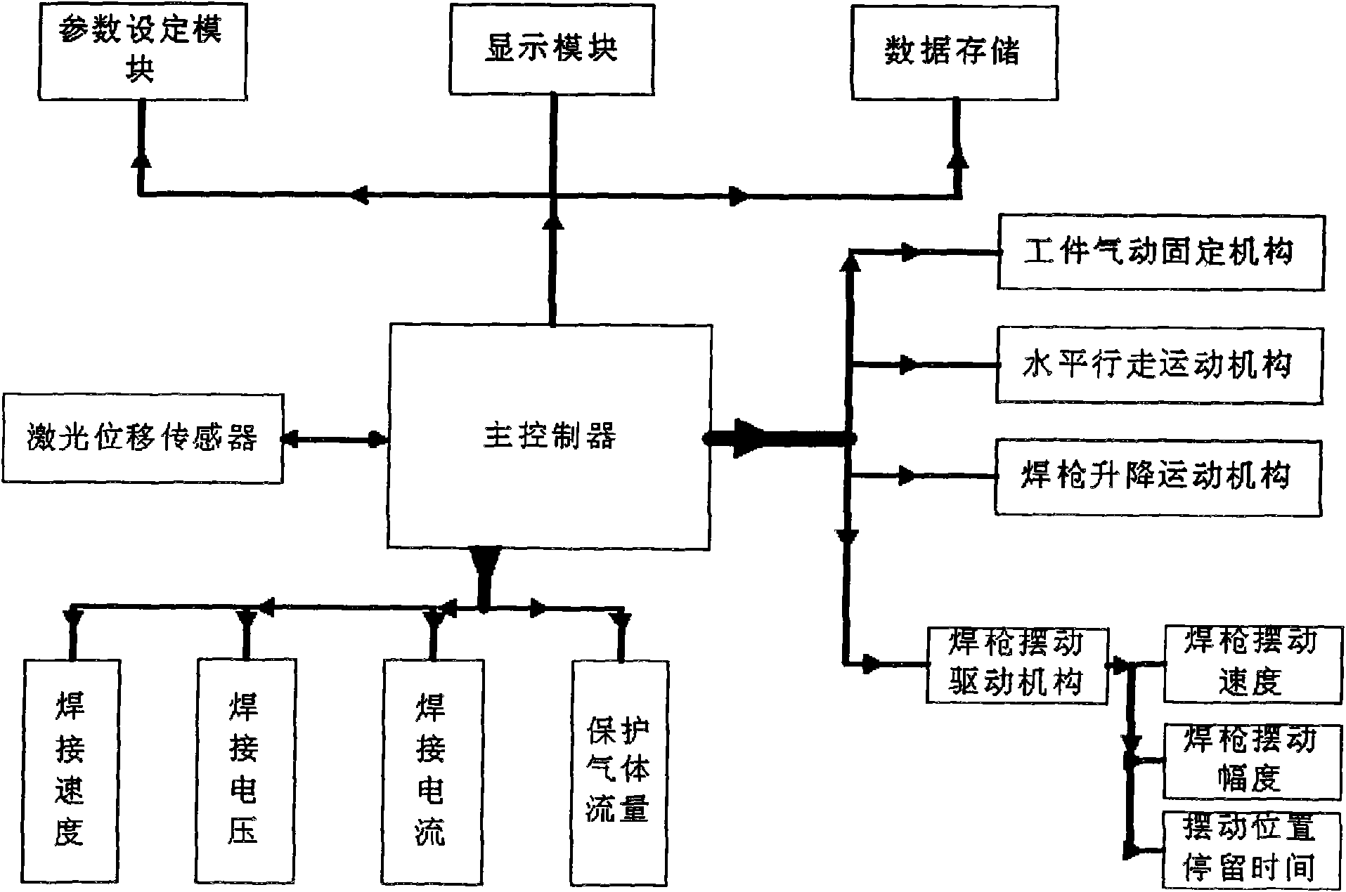
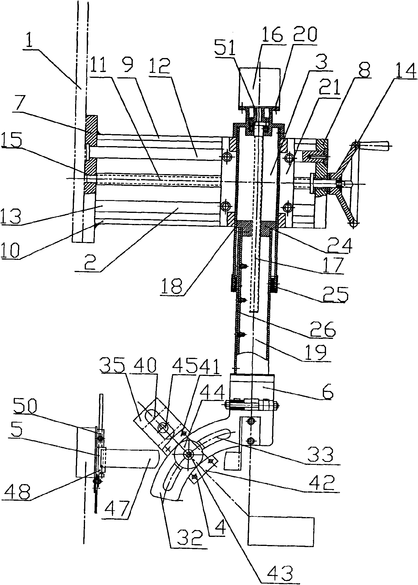
[0044] Figure 1-15 Among them, the laser displacement sensor 54 and the welding torch position adjustment device are connected with the circuit control device through a line.

[0045] One end of the welding torch spatial position and attitude adjustment mechanism is fixed on the frame 1, and the laser displacement sensor 54 is arranged at the lower end of the welding torch spatial position and attitude adjustment mechanism. The lifting transmission part of the welding torch in the mechanism is driven by a servo motor, which drives the welding torch to adjust up and down. At the same time, the mechanism allows the adjustment of the inclination angle of the welding torch to meet the requirements of different welding processes. It can also realize the zigzag welding wire swing. The swing device is driven by a stepping motor and controlled by the main con...


PUM


Abstract

The invention relates to a detection and control system for a container corrugated plate welding track based on laser ranging, comprising a laser displacement sensor, a welding torch pose adjusting device and a circuit control device. The laser displacement sensor and the welding torch pose adjusting device are connected with the circuit control device through a circuit; one end of a welding torch space position and pose adjusting mechanism is fixed on a stand; and the laser displacement sensor is arranged at the lower end of the welding torch space position and pose adjusting mechanism. Through the diction of the corrugated plate welding line, the control of the welding torch pose and the automatic control of the welding process, the invention achieves the effect that the thickness of welding lines of a downslope welding section from a wave crest to a wave trough, a upslope welding section from a wave trough to a wave crest, a wave crest tangential path and a wave trough are consistent, remarkably improves the uniformity of welding lines of each welding section, greatly reduces the labor intensity of workers, reduces the manual expense of production and is fast and convenient to adjust parameters. The welding speed is more than three times of general manual welding or profile modeling welding, and automatic control is available in the whole process.

Description

technical field [0001] The invention relates to a container corrugated plate welding trajectory detection and control system, in particular to a container corrugated plate welding trajectory detection and control system based on laser ranging. Background technique [0002] At present, my country is the world's largest producer of containers, and container manufacturing is a labor-intensive and material-intensive industry. At present, the production process of my country's containers, especially the welding of corrugated plates, is mainly based on manual welding and mechanical profiling semi-automatic welding. The working environment of workers is poor, the labor intensity is high, and the welding quality is difficult to control. At the same time, due to the inability to effectively track and adjust the welding specifications during the welding process, the quality of the welds formed by different slope sections is significantly different, and it is difficult to meet the weldi...

Claims


Application Information

Patent Timeline
Patent Type & Authority Applications(China)
IPC IPC(8): B23K9/095G05D3/12G05B15/02B23K9/127G01B11/00B21C37/08
Inventor 田新诚张光先刘涛
Owner SHANDONG UNIV
Why Eureka
Try Eureka