Device for heat-treating sheet metal strips

a technology of sheet metal strips and heat treatment, which is applied in the direction of heat treatment apparatus, furnaces, combustion types, etc., can solve the problems of reducing the strength of steels used and causing cracks, and achieves sufficient length compensation, reduced thermal strain of bearing pins, and substantial tension free

Inactive Publication Date: 2012-09-06
EBNER-INDUSTRIEOFENBAU GMBH
View PDF2 Cites 3 Cited by
  • Summary
  • Abstract
  • Description
  • Claims
  • Application Information

AI Technical Summary

Benefits of technology

[0005]Through the bridge which bridges the gusset area between the two pipe elbows, an advantageous condition is provided for accommodating thermal expansions in the area of the pipe elbows, so that the connection between the bearing pin and the bridge can be kept substantially tension-free. In addition, a direct heat transfer from the pipe elbows to the bearing pin is suppressed by the bridge, whereby the thermal strain of the bearing pin is reduced. In order that thermal expansions in the area of the two pipe elbows can advantageously be accommodated via the bridge, the bridge has two sections extending on both sides of the axis of the middle pipe and inclined at an acute angle to the axis of the middle pipe, so that through an angle change of the sections of the bridge inclined to one another at an obtuse angle, because of bending strains occurring in the elastic range, a sufficient length compensation is possible upon a thermal expansion of the pipe elbows.
[0006]Particularly simple design conditions result in this context if the bridge is implemented as symmetrical to the axis of the metal pipe, because in this case the coaxial mounting of the radiator unit to the middle pipe can be ensured in a simple manner.

Problems solved by technology

However, because thermal expansions occur not only in the direction of the pipe axes, but rather also in the area of the pipe elbows transversely thereto, a significant strain of the weld seams results between the bearing pin and the pipe elbows, which results in the danger of cracking, in particular because the strength of the steels used is reduced because of the high temperature strain.

Method used


Image

  • Device for heat-treating sheet metal strips
  • Device for heat-treating sheet metal strips
  • Device for heat-treating sheet metal strips

Examples


Embodiment Construction

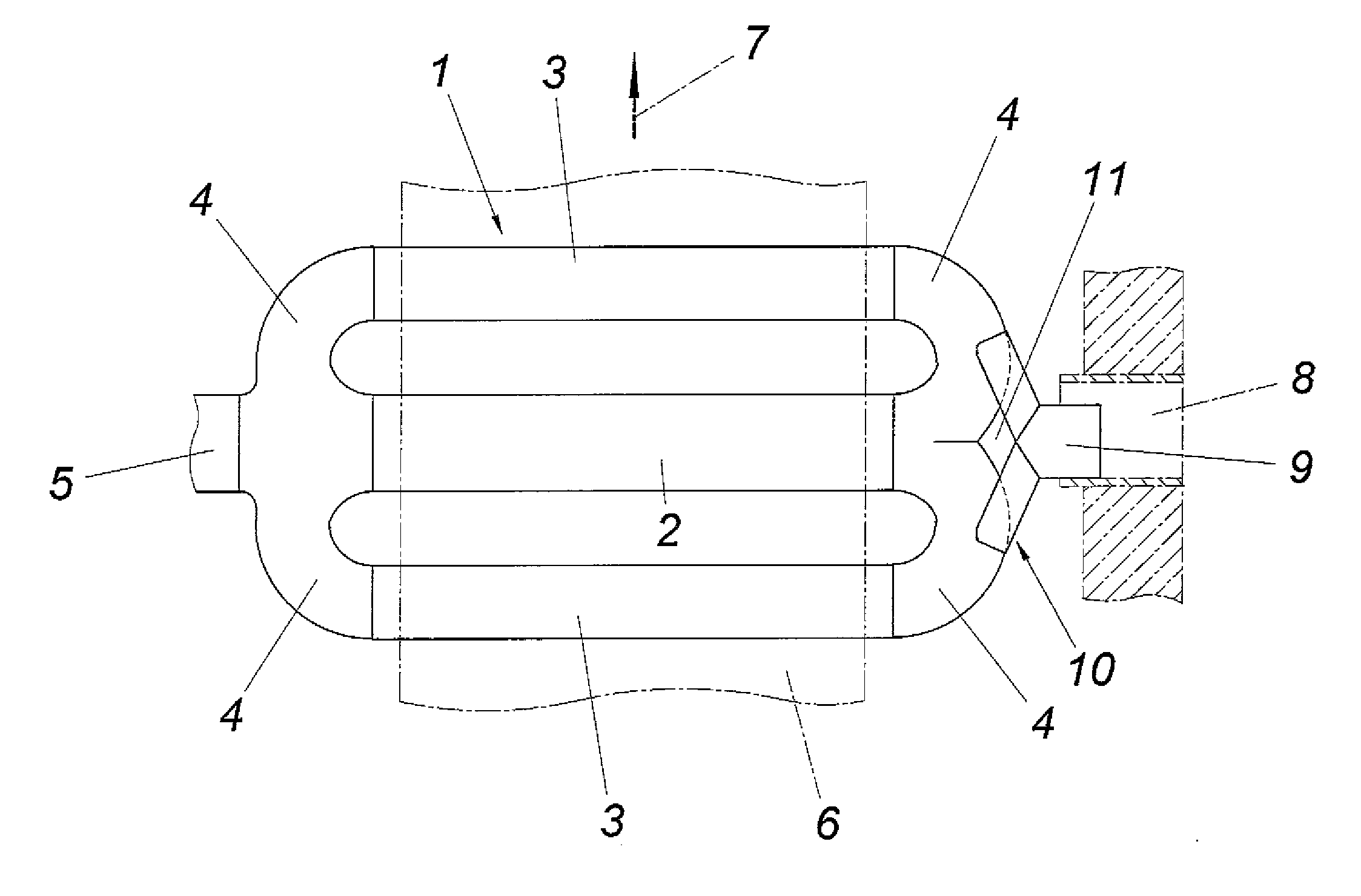
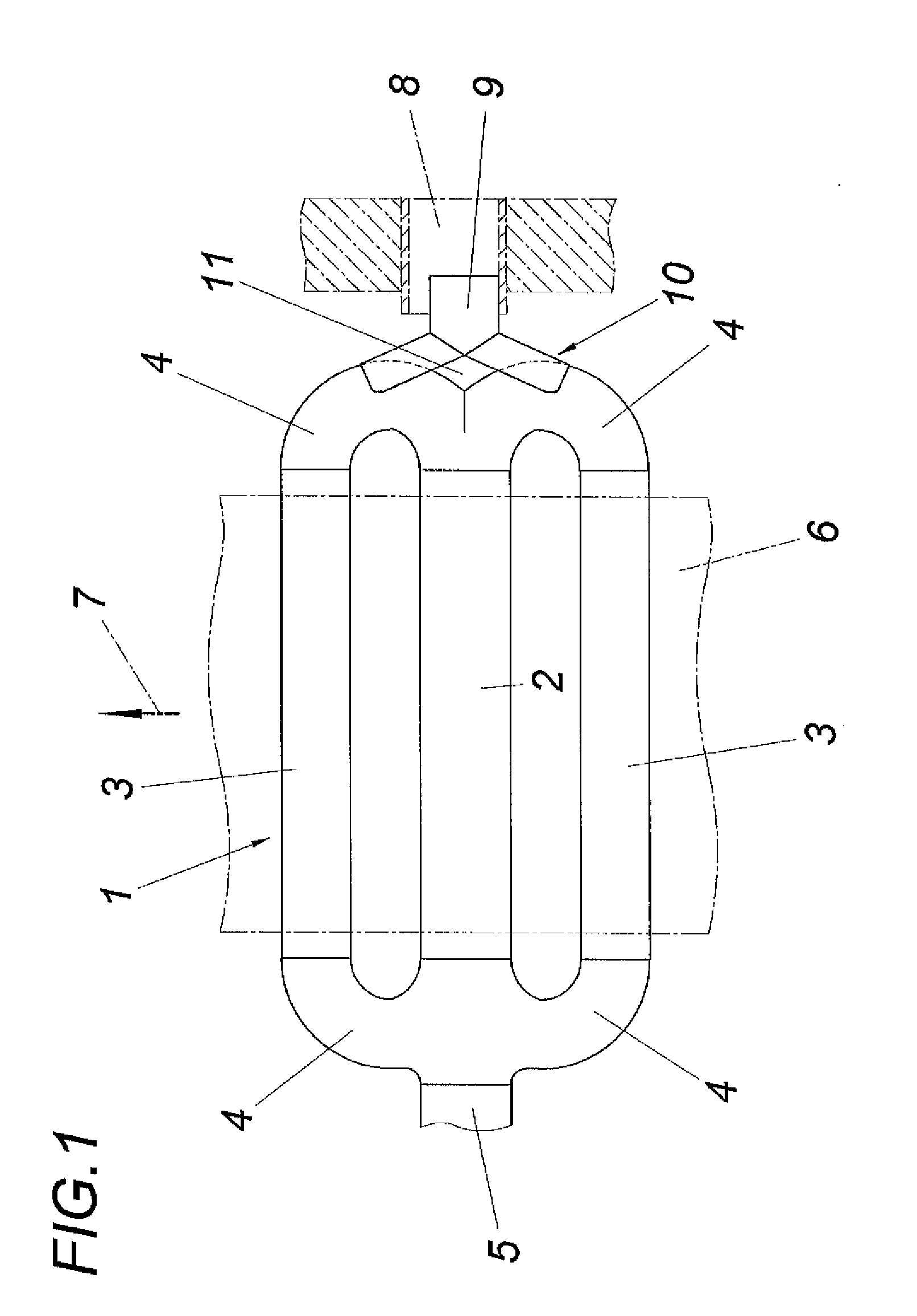
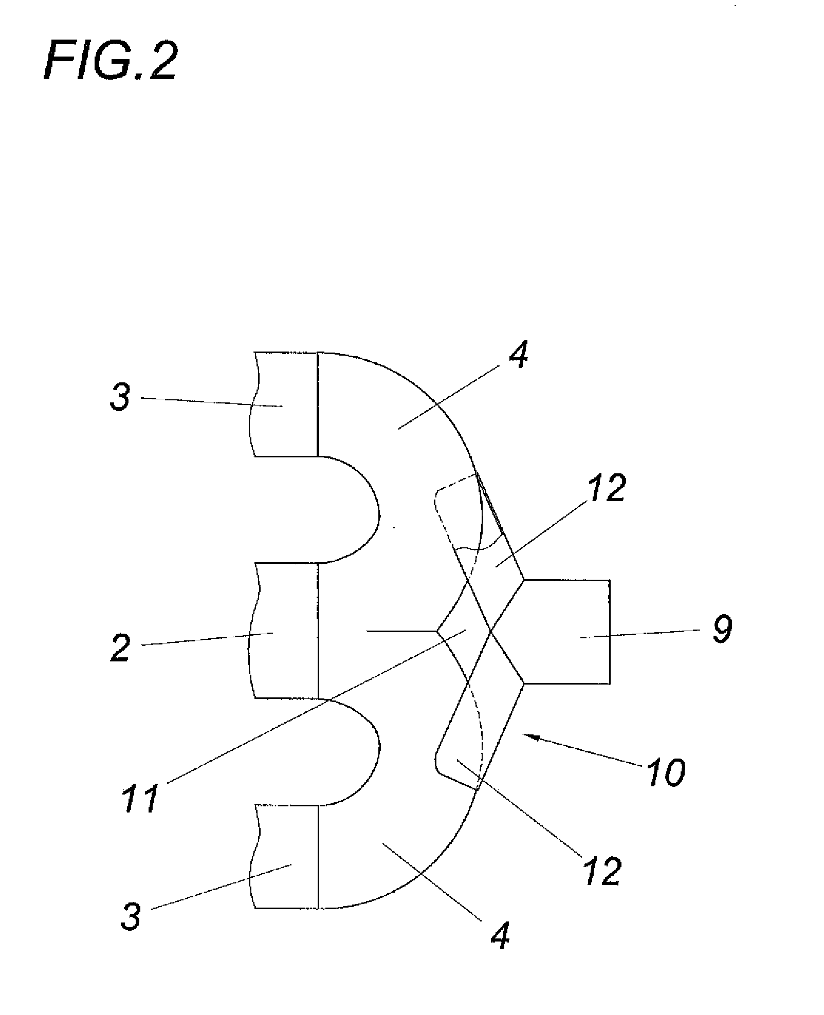
[0010]As can be inferred from FIG. 1, the device for heat-treating sheet metal strips has at least one radiator pipe unit 1, which comprises a middle pipe 2 and two parallel outer pipes 3 located in a common axial plane with the middle pipe 2. The outer pipes 3 each have a flow connection to the middle pipe 2 via terminal pipe elbows 4. The hot exhaust gases flowing from a burner, which is attached to an extension 5 of the middle pipe 2, into the middle pipe 2 are therefore partially guided in the circuit via the two outer pipes 3. A sheet-metal strip 6, which is indicated by dot-dash lines, and which is guided parallel to the common axial plane of the pipes 2, 3, in a feed direction 7 which extends transversely to the pipe axes, is heated with the aid of the radiant heat emitted from the pipes 2, 3.

[0011]The radiator pipe unit 1 is mounted on both sides of the pipes 2 and 3, so that a substantially uniform distribution of the weight load on the two supports results. While the suppo...


PUM

PropertyMeasurementUnit
temperaturesaaaaaaaaaa
thermal expansionsaaaaaaaaaa
strengthaaaaaaaaaa

Abstract

A device is described for heat-treating sheet metal strips (6) having at least one radiator pipe unit (1), which has three pipes located in a common axial plane parallel to the sheet-metal strip (6), namely one middle pipe (2) attachable to a burner and two outer pipes (3) connected at both ends to the middle pipe (2) via pipe elbows (4), and having a bearing pin (9), connected to the two pipe elbows (4) between the middle pipe (2) on one side and the two outer pipes (3) on the other side, on the side of the radiator pipe unit opposite to the burner. To be able to take the occurring thermal expansions in the area of the pipe elbows (4) into consideration, it is proposed that the bearing pin (9) be arranged on a bridge (10), which bridges a gusset (11) between the two pipe elbows (4), having two sections (12) which extend on both sides of the axis of the middle pipe (2) and are inclined at an acute angle to the axis of the middle pipe (2).

Description

FIELD OF THE INVENTION[0001]The invention relates to a device for heat-treating sheet metal strips having at least one radiator pipe unit, which has three pipes located in a common axial plane parallel to the sheet-metal strip, namely one middle pipe connectable to a burner and two outer pipes connected at both ends to the middle pipe via pipe elbows, and having a bearing pin, which is connected to the two pipe elbows between the middle pipe on one side and the two outer pipes on the other side, on the side of the radiator pipe unit opposite to the burner.DESCRIPTION OF THE PRIOR ART[0002]For heat-treating sheet metal strips (DE 20 2008 009 065 U1), providing radiator pipe units which can be heated with the aid of burners is known, which have two outer pipes originating from a middle pipe connected to the burner, located parallel to the middle pipe in a common axial plane, so that with the aid of the outer pipes connected terminally via pipe elbows to the middle pipe, a partial stre...

Claims


Application Information

Patent Timeline
Patent Type & Authority Applications(United States)
IPC IPC(8): C21D9/54
CPCF23C3/002F23C2900/03009F23D14/12F27D99/0035F23M9/003F23M9/08F23D21/005F23D91/02F23D14/126C21D9/52
Inventor EBNER, ROBERTMORBITZER, EDUARD
Owner EBNER-INDUSTRIEOFENBAU GMBH
Why Eureka
Try Eureka