Industrial vapour generator for the deposition of an alloy coating onto a metal strip

a vapour generator and alloy coating technology, applied in the field of metal strips, can solve the problems of contaminated baths of molten metal, increased mechanical difficulty, and inability to deposition alloy coatings normally

Active Publication Date: 2011-01-06
ARCELORMITTAL INVESTIGACION Y DESARROLLO SL
View PDF29 Cites 40 Cited by
  • Summary
  • Abstract
  • Description
  • Claims
  • Application Information

AI Technical Summary

Benefits of technology

[0033]According to Claim 1, the present invention relates to a vapour generator for depositing a metal coating on a substrate, preferably a steel strip, comprising a vacuum chamber in the form of a housing, equipped with a means for ensuring a low-pressure state relative to the external environment and equipped with a means for allowing the entry and exit of the substrate, whilst being more or less sealed relative to the external environment, said housing surrounding a vapour deposition head, called an ejector, shaped so as to create a jet of metal vapour at the speed of sound in the direction of and perpendicular to the surface of the substrate, said ejector being

Problems solved by technology

Such an alloy deposition is not normally possible with the usual techniques such as electrolytic deposition, dip coating, etc.
With dipping at atmospheric pressure, for instance, the bath of molten metal may be contaminated by the oxygen in the air, which forms oxides on the surface of the bath.
One solution would be to skim the surface or to recycle thecharge but any mechanical operation is made more difficult in a vacuum;the difficulty of adjusting the evaporation slit to a variable strip width, which entails a means for blocking the slit on both sides, and thus the creation of a vapour-tight seal in a vacuum and at 700° C., which is not easy to achieve;the difficulty of blocking the slit when the motion of the strip is interrupted, which would entail the presence of a linear valve seal

Method used


Image

  • Industrial vapour generator for the deposition of an alloy coating onto a metal strip
  • Industrial vapour generator for the deposition of an alloy coating onto a metal strip
  • Industrial vapour generator for the deposition of an alloy coating onto a metal strip

Examples


Embodiment Construction

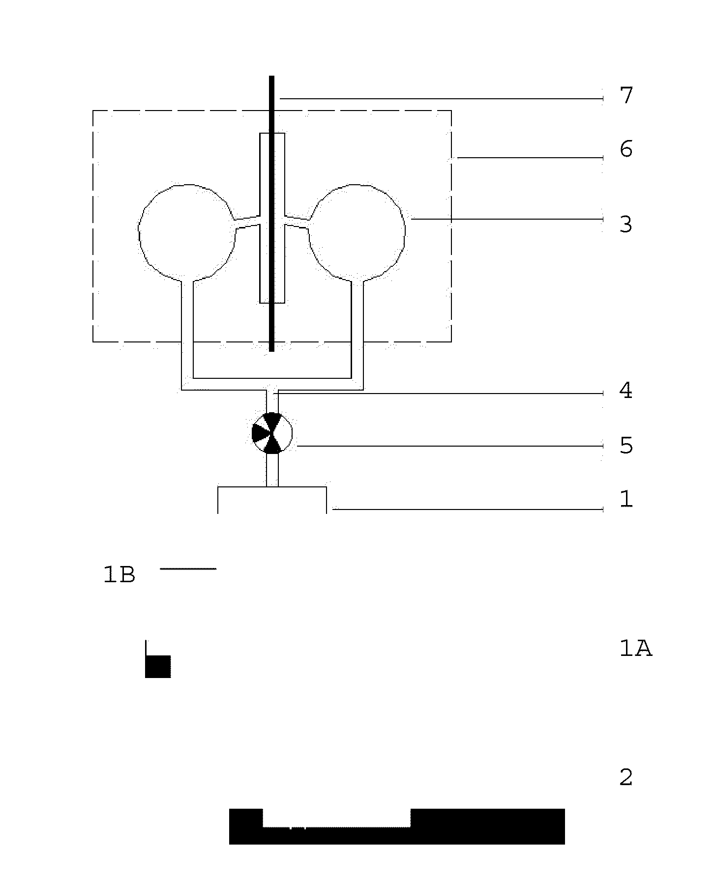
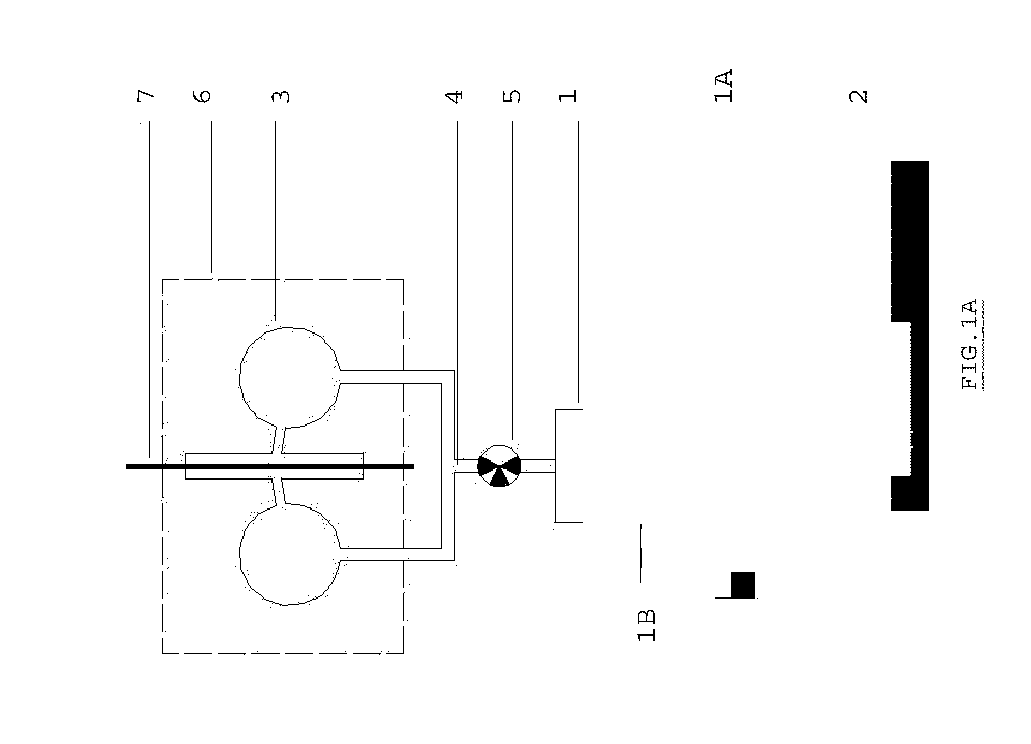
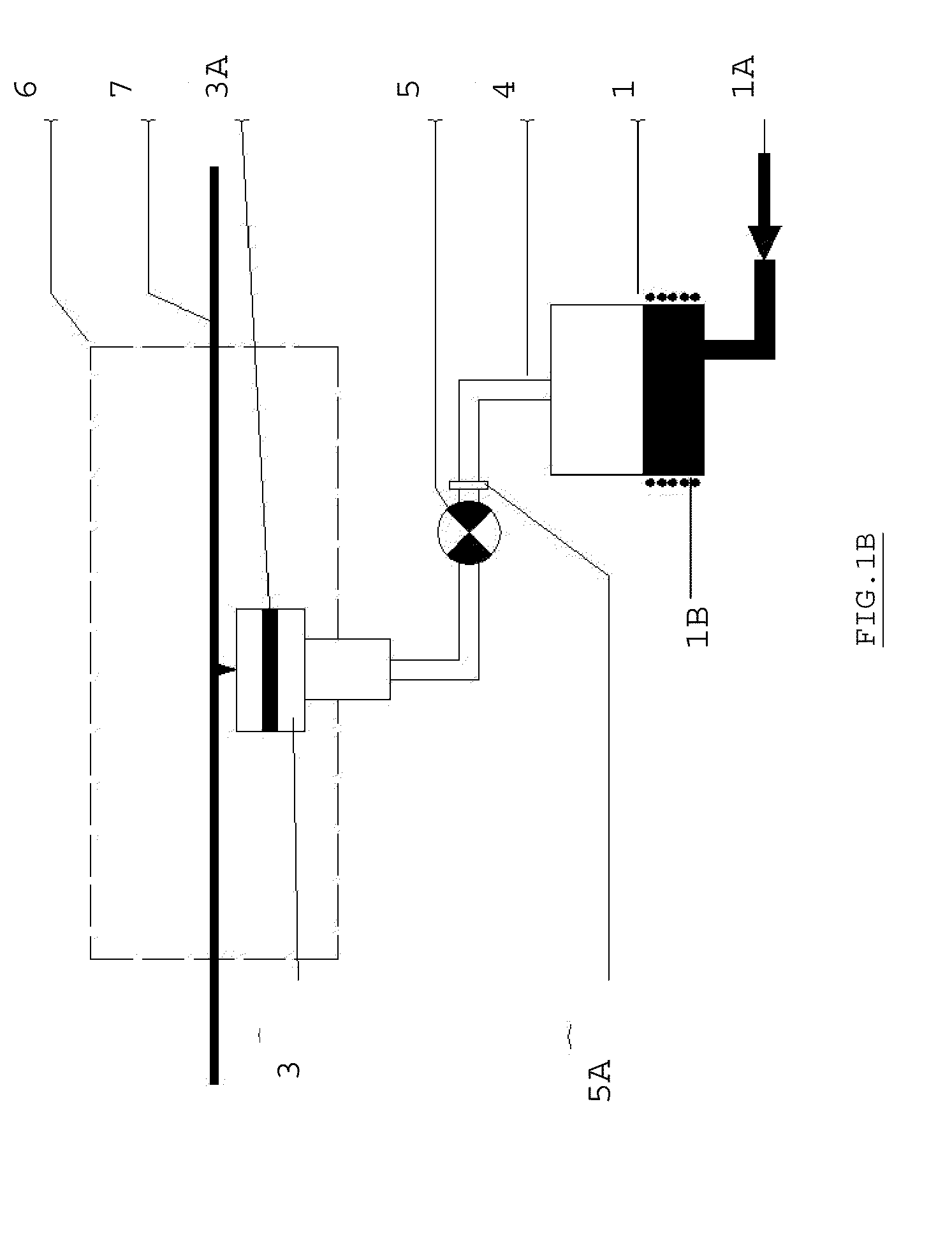
[0061]The solution recommended by the present invention consists in using an evaporation crucible that is separated from a JVD ejection head with a longitudinal vapour outlet slit, herein after called an ejector. The general principle of such a device is shown in FIG. 1A. Another schematic view is given in FIG. 1B. An overview description of a pilot installation is provided in FIG. 1C. The crucible 1 is fed by a pipe 1A from a magnesium melting furnace 2, with the impurities being decanted. The type of melting furnace and the pipes used are equipment normally used in the foundry industry and are well know to the man skilled in the art. In particular, the melting and charging in the device as in the invention are carried out by tried and tested techniques.

[0062]With the crucible 1 being displaced and of a cylindrical shape, a high level of uniformity of temperature may be achieved thanks to vigorous magnetic stirring. The magnetic stirring performed by an inductor 1B attached to this...


PUM

PropertyMeasurementUnit
Currentaaaaaaaaaa
Currentaaaaaaaaaa
Digital informationaaaaaaaaaa

Abstract

The invention relates to a vapour generator for the deposition of a metal coating onto a substrate (7), preferably a steel strip, that comprises a vacuum chamber (6) in the form of a housing including a vapour deposition head or ejector (3) in tight communication via a supply duct (4) with at least one crucible (1) containing the coating metal in a liquid form and located outside the vacuum chamber (6), characterised in that the ejector (3) includes a longitudinal slot for the vapour outlet acting as a sonic throat and extending on the entire width of the substrate (7), a filtration medium or a charge loss member (3A) made of a sintered material being provided in the ejector immediately before said slot on the vapour path in order to equalise the flow speed of the vapour exiting the ejector (3) through the sonic throat.

Description

FIELD OF THE INVENTION[0001]The present invention relates to an industrial vapour generator for the continuous coating in vacuum of a substrate in motion, more particularly a metal strip, by means of a metal vapour so as to form a metal layer, preferably a metal alloy layer, on its surface in such a way as to give it excellent resistance to corrosion whilst preserving good drawing and welding features.STATE OF THE ART[0002]It has been known since the end of the 1980's that the deposition of specific alloys such as ZnMg on the surface of a steel strip acts as protection for the steel. The excellent corrosion behaviour of ZnMg alloy is attributed to the nature of the corrosion products formed on the surface of the strip in an extremely dense layer, which acts as a barrier film.[0003]Such an alloy deposition is not normally possible with the usual techniques such as electrolytic deposition, dip coating, etc. With dipping at atmospheric pressure, for instance, the bath of molten metal m...

Claims


Application Information

Patent Timeline
IPC IPC(8): C23C16/52C23C16/06
CPCC23C14/16C23C14/562C23C14/243
Inventor BANASZAK, PIERREMARNEFFE, DIDIERSILBERBERG, ERICVANHEE, LUC
Owner ARCELORMITTAL INVESTIGACION Y DESARROLLO SL
Why Eureka
Try Eureka