

Ink-jet recording process, ink-jet recording apparatus and image formed article
a recording head and inkjet technology, applied in the direction of measuring apparatus components, instruments, printing, etc., can solve the problems of clogging of recording head orifices, inability to obtain color images with good fastness properties and image quality, and complicated construction of the apparatus
- Summary
- Abstract
- Description
- Claims
- Application Information
AI Technical Summary
Benefits of technology
Problems solved by technology
Method used
Image

Examples
experimental examples 22 to 42
The construction of a recording head unit of a recording apparatus used in Experimental Examples 22 to 42 comprises a Bk1 chip 2001, an S chip 2002 and a Bk2 chip 2003 as illustrated in FIG. 4. The individual chips are arranged on a frame 2004 in an inclined relation with them compensating by timing of drive at a pitch of 1 / 2 inch. The number of nozzles in each chip is 64, and a nozzle line in each chip is arranged so as to intersect almost perpendicularly to the direction of an arrow X. The pitch of each nozzle is about 70 .mu.m, and the use of such a head permits the recording of a band of 64 nozzles with resolution of 360 dpi by one main scanning. In these experimental examples, the application of the ink was conducted in two installments of 40 pl by means of two nozzle chips, Bk1 chip 2001 and Bk2 chip 2003.
As the individual chips used in Experimental Examples 22 to 42, those separately having heating elements with heating values according to the amounts of a liquid composition ...
experimental example 43
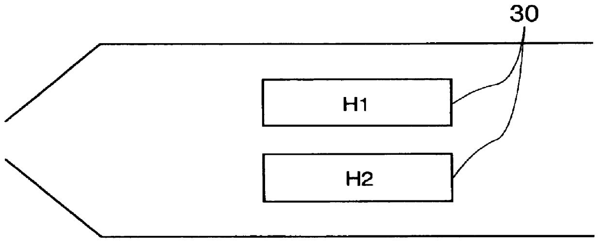
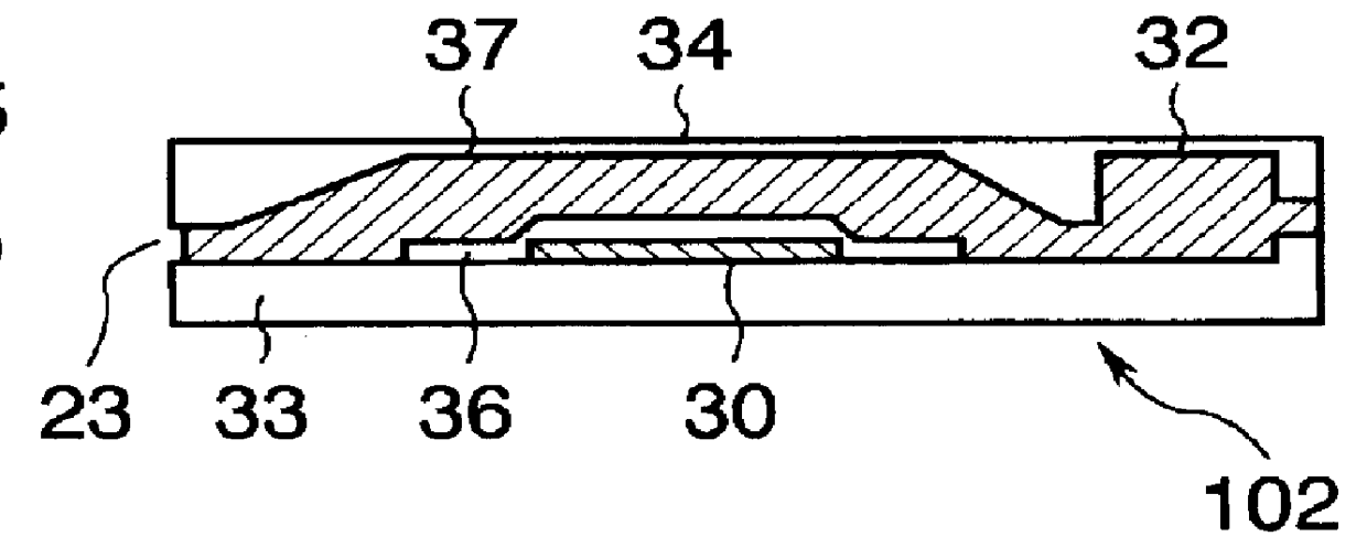
In this experimental example, a recording head having two heating elements H1 and H2 in each nozzle as illustrated in FIG. 2 was used.
The construction of a recording head unit comprises an S chip 2301 and a Bk chip 2302 as illustrated in FIG. 3. The individual chips are arranged on a frame 2304 in an inclined relation with them compensating by timing of drive at a pitch of 1 / 2 inch. The number of nozzles in each chip is 64, and a nozzle line in each chip is arranged so as to intersect almost perpendicularly to the direction of an arrow X. The pitch of each nozzle is about 70 .mu.m, and the use of such a head permits the recording of a band of 64 nozzles with resolution of 360 dpi by one main scanning. Incidentally, the Bk and S chips used in this experimental example were the same.
The amount of the ink or liquid composition ejected from the recording head used in this experimental example is about 25 pl where energy is applied only to the heating element H1, about 40 pl where energy...
experimental example 44
In this experimental example, a recording head having two heating elements H1 and H2 in each nozzle as illustrated in FIG. 2 was also used.
The construction of a recording head unit comprises a Bk1 chip 2001, an S chip 2002 and a Bk2 chip 2003 as illustrated in FIG. 4. The individual chips are arranged on a frame 2004 in an inclined relation with them compensating by timing of drive at a pitch of 1 / 2 inch. The Bk1, S and Bk2 chips used in this experimental example were the same.
As with the head used in Experimental Example 43, the amount of the ink or liquid composition ejected from the recording head is about 25 pl where energy is applied only to the heating element H1, about 40 pl where energy is applied only to the heating element H2, and about 70 pl where energy is applied to both heating elements H1 and H2. The minute regulation of the ejection quantities was carried out by changing a pulse length further applied to the heating elements H1 and H2 to control energy applied to the...
PUM
 Abstract
Description
Claims
Application Information