Inverted-F antenna

a technology of inverted f antennas and antenna earthings, which is applied in the direction of resonant antennas, antenna earthings, radiating element structural forms, etc., can solve the problems of complex antenna construction, poor impedance matching, and several prior art problems, and achieve the lowest capacitance rate, perfect impedance matching, and increase the bandwidth and efficiency of antennas

Inactive Publication Date: 2007-02-27
ADVANCED CONNECTEK INC
View PDF6 Cites 39 Cited by
  • Summary
  • Abstract
  • Description
  • Claims
  • Application Information

AI Technical Summary

Benefits of technology

[0007]The object of the present invention is to provide an innovative design of an inverted-F antenna, which could increase the bandwidth and efficiency of the antenna to meet the bandwidth requirements of the system frequency band.
[0009]In the present design, the first child radiating metal sheet is located on the first lateral side of the dielectric substrate, i.e. it is on the remotest position from the system ground surface. Therefore, it could have a lowest capacitance rate between the radiating metal sheet and the system ground surface. The energy has a better radiating effect. The system ground surface uses a gap mode, which could decrease the capacitance rate between the radiating metal sheet and the system ground surface similarly. It improves the bandwidth and efficiency of the antenna in large scale. Therefore it could achieve a broader band antenna by adjusting the gap portion of the ground surface properly. It could achieve a dual frequency antenna to fit the system bandwidth requirements.

Problems solved by technology

However, construction of the antenna can be very complicated for meeting the above requirements and needs.
However, the prior art suffered from several disadvantages.
Further, its construction is relatively complicated.
Furthermore, the surface current pathways are meandered, resulting in a narrowing of bandwidth (i.e., only suitable for dual-band applications).
Moreover, its adjustment is difficult in practice.

Method used


Image

  • Inverted-F antenna
  • Inverted-F antenna
  • Inverted-F antenna

Examples


first embodiment

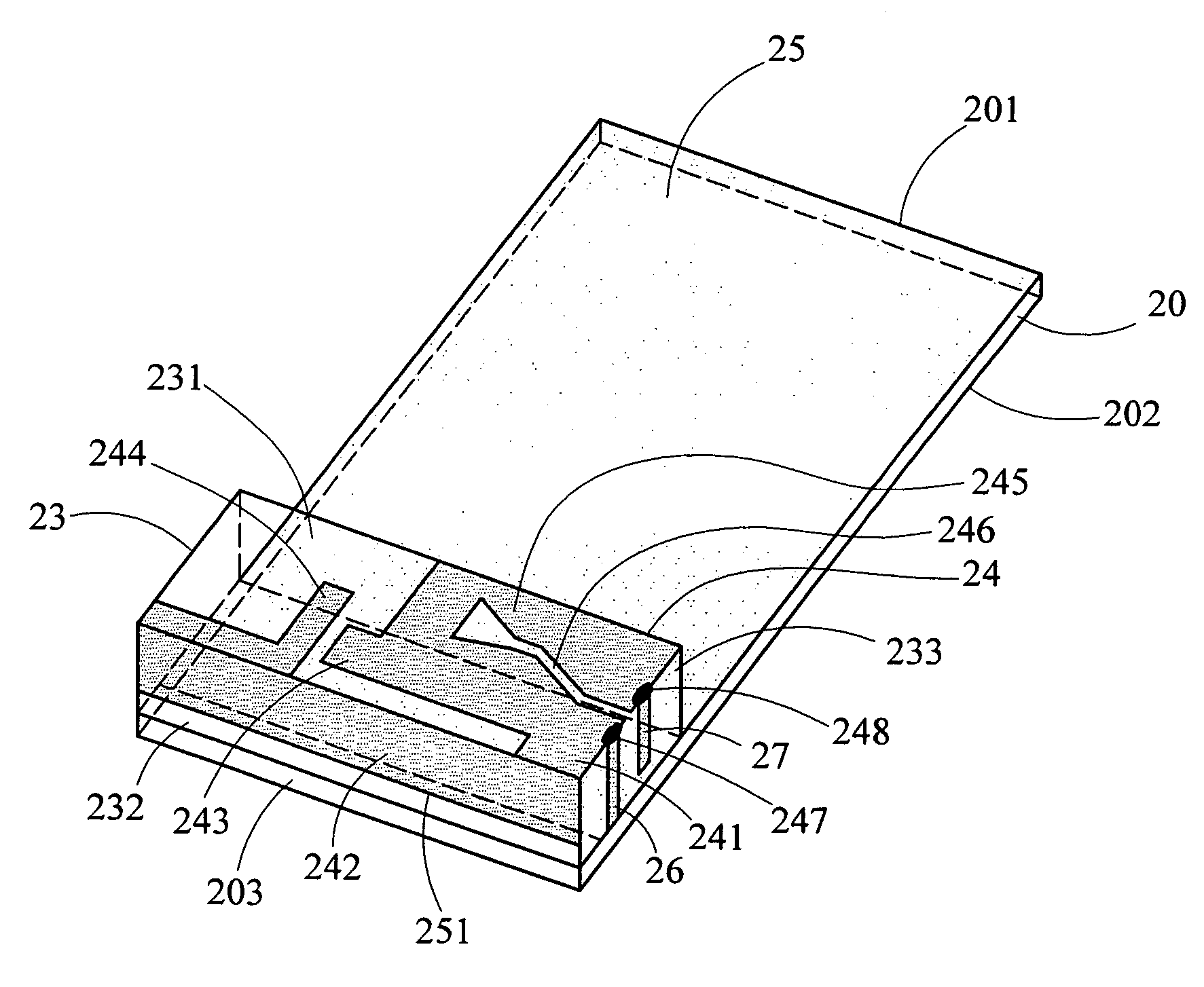
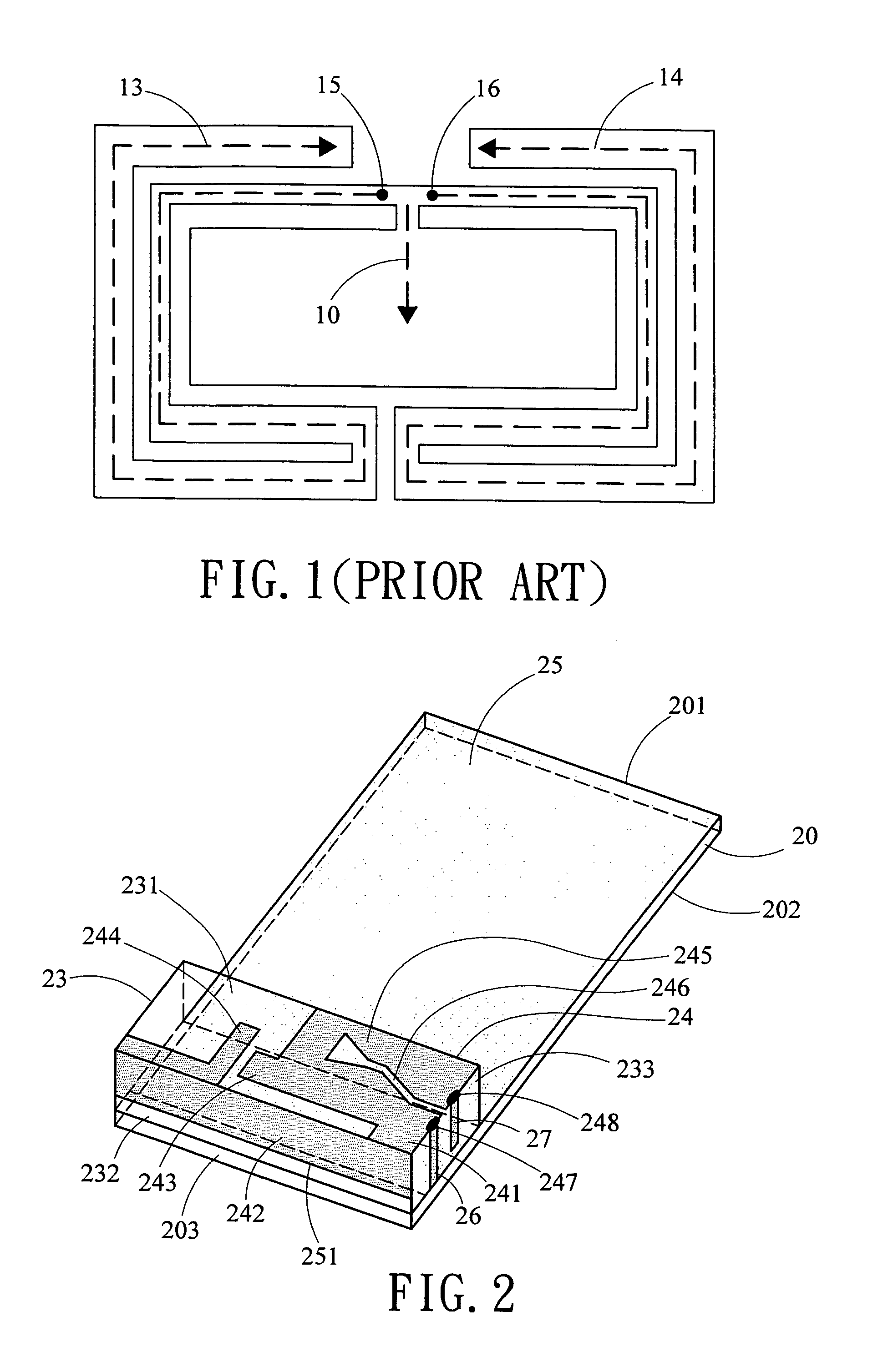
[0014]As shown in FIG. 2, an inverted-F antenna of the present invention comprises a microwave plate 20, a dielectric substrate 23, a radiating metal sheet 24, a ground surface 25, a shorting metal strip 26 and a feeding metal strip 27.

[0015]The microwave plate 20 has a first surface 201 and a second surface 202.

[0016]The dielectric substrate 23 located on the upper side of the first surface 201 of the microwave plate 20 has an upper surface 231, two first lateral sides 232 and two second lateral sides 233. In practice, the dielectric substrate 23 could be air or a plastic material of which the dielectric constant is about 1. Thereinto, the outer first lateral side 232 is adjacent to and generally parallel to the short edge 203 of the microwave plate 20. The second lateral side 233 is perpendicular to the first lateral side 232. The length of the first lateral side 232 is longer than that of the second lateral side 233.

[0017]The radiating metal sheet 24 comprises a connecting metal ...

second embodiment

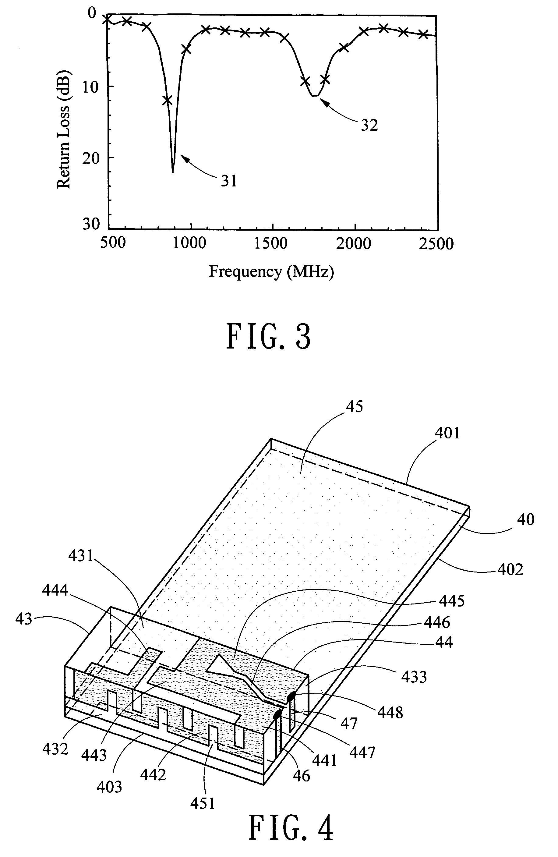
[0022]As shown in FIG. 4, an inverted-F antenna of the present invention comprises a microwave plate 40, a dielectric substrate 43, a radiating metal sheet 44, a ground surface 45, a shorting metal strip 46 and a feeding metal strip 47.

[0023]The microwave plate 40 has a first surface 401 and a second surface 402.

[0024]The dielectric substrate 43 located on the upper side of the first surface 401 of the microwave plate 40 has an upper surface 431, two first lateral sides 432, and two second lateral sides 433. The dielectric substrate 43 could be air or a plastic material of which the dielectric constant is about 1. Thereinto, the outer first lateral side 432 is adjacent to and generally parallel to the short edge 403 of the microwave plate 40. The second lateral side 433 is perpendicular to the first lateral side 432. The length of the first lateral side 432 is longer than that of the second lateral side 433.

[0025]The radiating metal sheet 44 comprises a connecting metal sheet 441, a...


PUM

PropertyMeasurementUnit
dielectric constantaaaaaaaaaa
frequency bandaaaaaaaaaa

Abstract

An inverted-F antenna comprises a microwave plate, a dielectric substrate, a radiating metal sheet, a ground surface, a shorting metal strip, and a feeding metal strip. The radiating metal sheet comprises a connecting metal sheet, first, second, and third child radiating metal sheets, a matching metal sheet, a slot, a shorting point, and a feeding point. The first child radiating metal sheet is for forming a low frequency operating mode. The second child radiating metal sheet is for forming a high frequency operating mode. The third child radiating metal sheet is for adjusting operating frequency and bandwidth of the second operating mode. The slot, the shorting point, and the feeding point are for adjusting impedance matching. The grounding surface is for increasing the operating bandwidth of the low frequency operating mode. The shorting metal sheet and the feeding metal sheet are for grounding the antenna and signal transmission.

Description

BACKGROUND OF THE INVENTION[0001]1. Field of the Invention[0002]The present invention relates generally to an antenna, especially to an inverted-F antenna applied in wireless communication products.[0003]2. Description of Related Art[0004]In recent years, wireless communication has known a rapid, spectacular development. Also, requirements for quality and performance of antenna mounted in a wireless communication device (e.g., cellular phone, PDA) are increased. In addition to the requirement of miniature antenna, multiple frequency band or ultra-wideband feature is also necessary for keeping up with the trend. Moreover, for aesthetic and practical purposes a miniature antenna is typically mounted within a wireless communication device (e.g., cellular phone). However, construction of the antenna can be very complicated for meeting the above requirements and needs. Thus, it is important to further improve the prior hidden antenna by fully taking advantage of the limited space in a wi...

Claims


Application Information

Patent Timeline
Patent Type & Authority Patents(United States)
IPC IPC(8): H01Q1/24H01Q1/38H01Q1/22H01Q1/36H01Q1/48H01Q5/00H01Q5/371H01Q9/04
CPCH01Q1/243H01Q5/371H01Q9/0421H01Q1/38
Inventor CHANG, PING-CHENGLIN, WEN-FACHIU, TSUNG-WENHSIAO, FU-REN
Owner ADVANCED CONNECTEK INC
Why Eureka
Try Eureka