
Broadband power amplifier

a power amplifier and broadband technology, applied in the field of communication front end modules, can solve the problems of low output impedance, high match drawback, and difficulty in implementing multi-band operation in a single pa while maintaining high efficiency characteristics, and achieve the effect of reducing the size and cost of the pa, increasing the bandwidth and efficiency of the broadband pas

Inactive Publication Date: 2013-10-22
SONY CORP
View PDF8 Cites 0 Cited by
  • Summary
  • Abstract
  • Description
  • Claims
  • Application Information

AI Technical Summary

Benefits of technology

The solution described in this patent improves the ability of broadband PAs (which are used in communication systems) to transmit information over multiple frequencies. By using a single PA die, the system can cover all desired frequencies, which makes the PAs smaller and less expensive. This is helpful for reducing the size and cost of communication devices.

Problems solved by technology

Improving the bandwidth and implementing multi-band operation in a single PA while maintaining high efficiency characteristics have proven difficult.
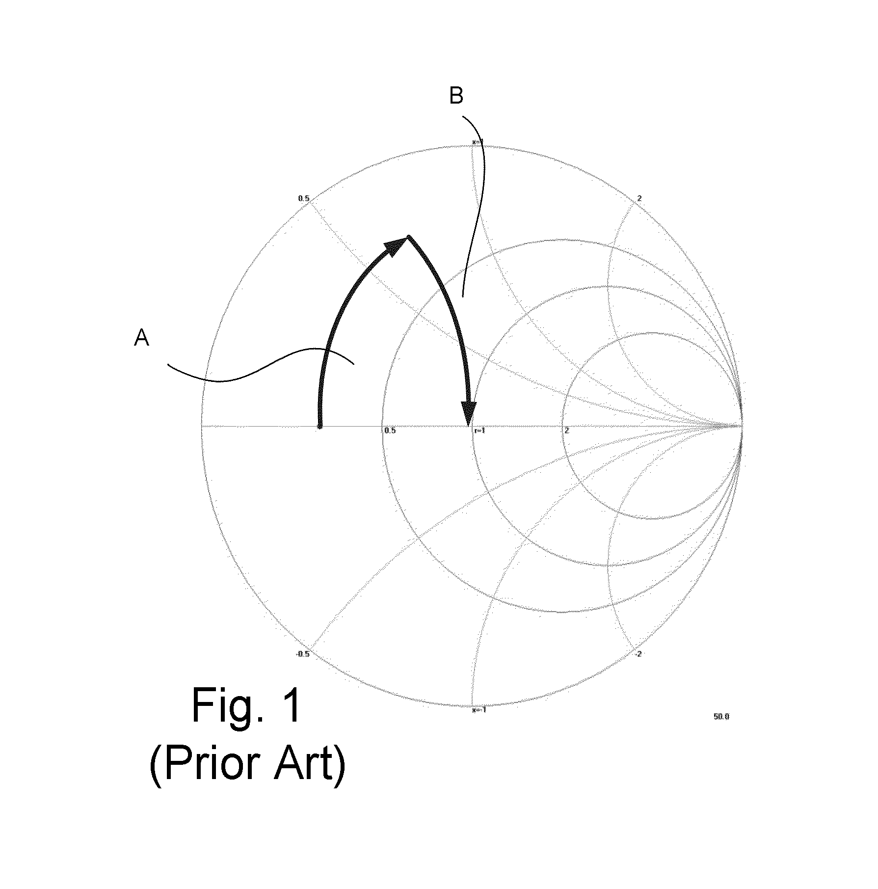
One problem with a PA is the low output impedance that has to be matched to, e.g. 50Ω.
The drawback is the high Q of the match.
This match will only work well for one frequency, hence the bandwidth will be poor and under no circumstances suitable for broadband PA's.
This may result in a much higher insertion loss and size compared to the high Q matching.
The higher insertion loss must be compensated resulting in decreased efficiency, higher current consumption and increased heating.
Modern broadband PA's are a trade off when it comes to insertion loss and bandwidth.

Method used


Image

  • Broadband power amplifier
  • Broadband power amplifier
  • Broadband power amplifier

Examples


Embodiment Construction

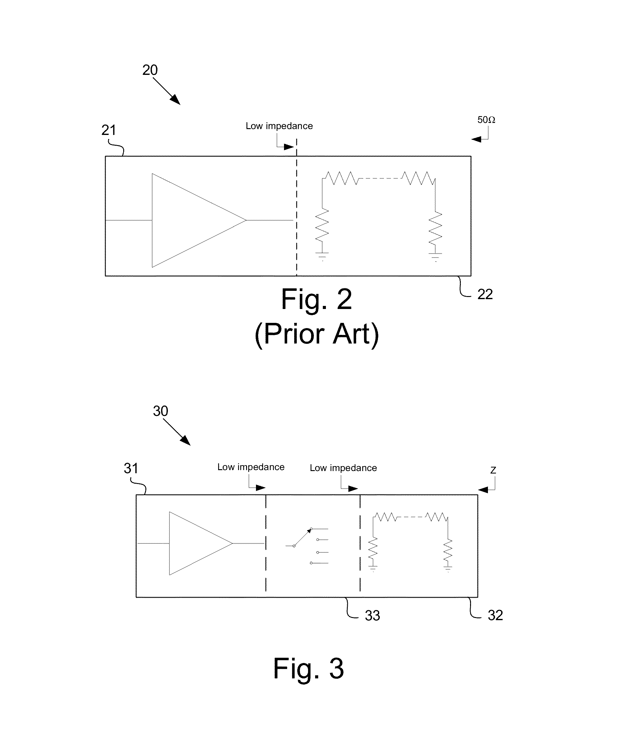
[0028]MEMS (MicroElectroMechanicalSystem) is the integration of mechanical elements, sensors, actuators, and electronics on a common substrate through microfabrication technology. This means that switches made from MEMS have their impedance decided by the physical dimensions rather than, for example bias voltage of PN transitions as is the case with current switches (e.g. PHEMT, diode, CMOS etc.). This means that the switch can operate at the same impedance as the output stage of the PA making switch matching not needed. The MEMS switch could then switch in the necessary matching making the output impedance (e.g. 50Ω / 75Ω, etc.) through a high Q, low insertion loss match.

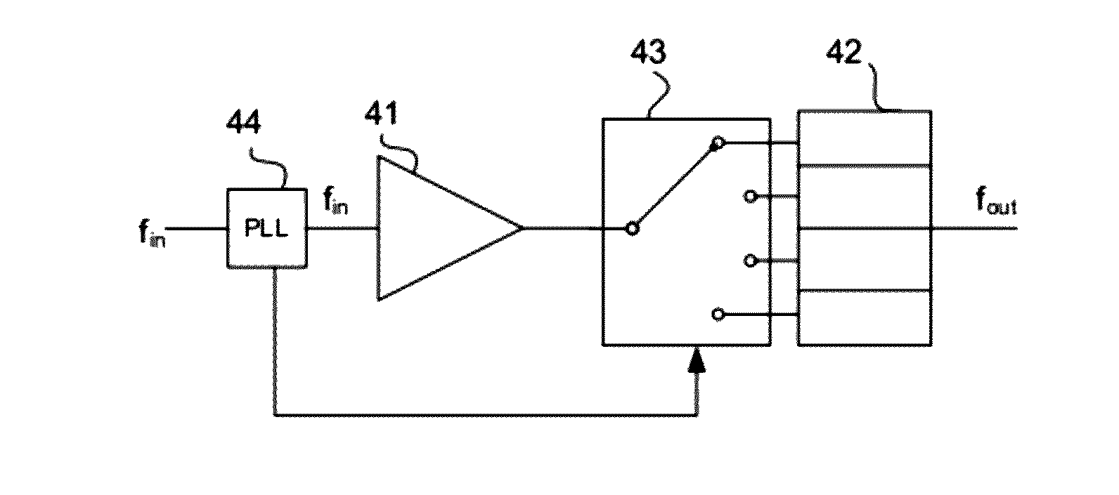
[0029]FIG. 3 is a first schematic embodiment of a power amplifier (PA) according to the invention. The PA module 30 comprises a power amplification stage 31, a matching stage 32 and a MEMS switch stage 33 between the amplification 31 and the matching stages 32. The MEMS switch stage 33 is arranged in series with the ...


PUM


Abstract

The present invention relates to a power amplifier unit (30, 40, 50, 60a-60d, 70) comprising a power amplifier element (31, 41, 51, 71) and a matching unit (32, 42, 52, 72). The unit comprises an impedance matched MicroElectroMechanicalSystem (MEMS) switch element (33, 43, 53, 73) between said power amplifier element (31, 41, 51, 71) and said matching unit (32, 42, 52, 72).

Description

TECHNICAL FIELD[0001]The present invention relates to a communication front end module in general and a broadband power amplifier having switchable matching in particular.BACKGROUND[0002]In recent years, due to multi-functionality of mobile communication terminals, relays, base stations, wireless network devices and satellite communication devices, many studies on improvement in the frequency bandwidth of the transmitters and receivers have been done. RF wideband power amplifiers are desirable as they reduce equipment, power consumption and operating cost for the RF communication infrastructure devices. Thus, a high performance power amplifier able to accommodate a wide range of frequency bands is desired.[0003]RF circuits are an essential element in the terminal and devices receiving and transmitting the radio waves. The RF circuit comprises individual circuits such as Power Amplifier (PA), for handling high frequency signals.[0004]The PA is key device in an RF circuit, which takes...

Claims


Application Information

Patent Timeline
Patent Type & Authority Patents(United States)
IPC IPC(8): H03F3/191
CPCH03F1/56H03F3/189H03F3/195H03F3/24H03F2200/36H03F2200/387H03F2200/414H03F2200/417H03F2200/421
Inventor SKARP, FILIPZANDER, OLOF
Owner SONY CORP
Learn More