Variable stator vane arrangement for a compressor

a stator vane and compressor technology, applied in the direction of engine starters, liquid fuel engines, lighting and heating apparatus, etc., can solve the problem of increasing the error or discrepancy in the angular position of the variable stator van

Inactive Publication Date: 2007-04-03
ROLLS ROYCE PLC
View PDF9 Cites 38 Cited by
  • Summary
  • Abstract
  • Description
  • Claims
  • Application Information

AI Technical Summary

Benefits of technology

[0008]Accordingly the present invention seeks to provide a novel variable stator vane arrangement for an axial flow compressor which reduces the above mentioned problem.
[0009]Accordingly the present invention provides a variable stator vane arrangement for an axial flow compressor comprising a compressor casing, a plurality of variable stator vanes, a control ring, a plurality of operating levers and a plurality of circumferentially extending strips, the variable stator vanes being circumferentially spaced apart and extending radially, each variable stator vane being rotatably mounted on the compressor casing, the control ring surrounding the compressor casing, each variable stator vane being connected to the control ring by a respective one of the plurality of operating levers, the control ring being spaced from the compressor casing by a clearance, the circumferentially extending strips being arranged circumferentially and being positioned radially between the control ring and the compressor casing, the strips control the clearance between the control ring and the compressor casing whereby any error of the variable stator vane angular position is reduced.

Problems solved by technology

However, if the control ring becomes distorted, or becomes eccentric, then the operating levers will move by differing amounts and the variable stator vanes will take up different angular positions.
These requirements result in an increased radial clearance between the compressor casing and the control ring, which increases the error or discrepancy in the variable stator vane angular position.

Method used


Image

  • Variable stator vane arrangement for a compressor
  • Variable stator vane arrangement for a compressor
  • Variable stator vane arrangement for a compressor

Examples


Embodiment Construction

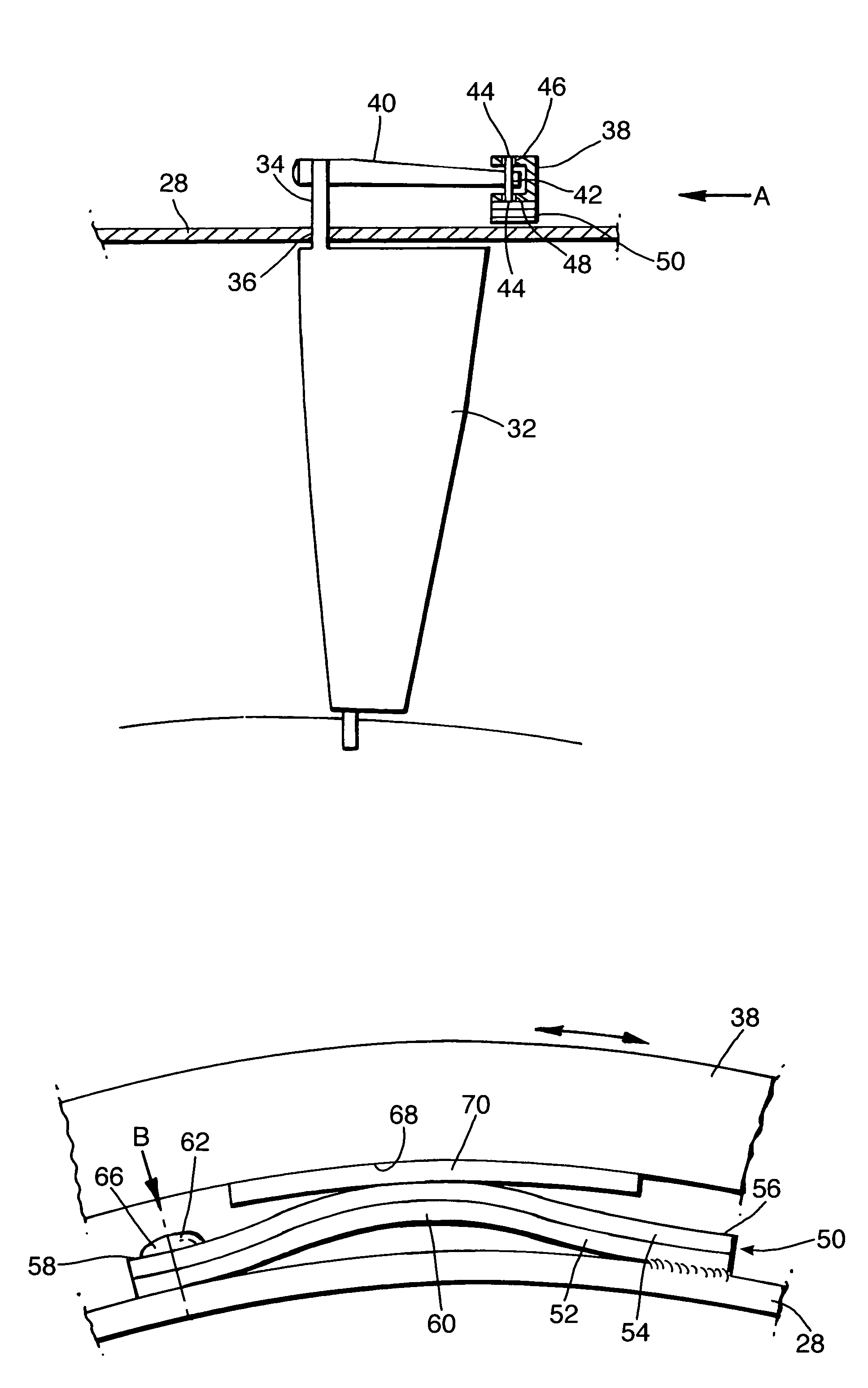
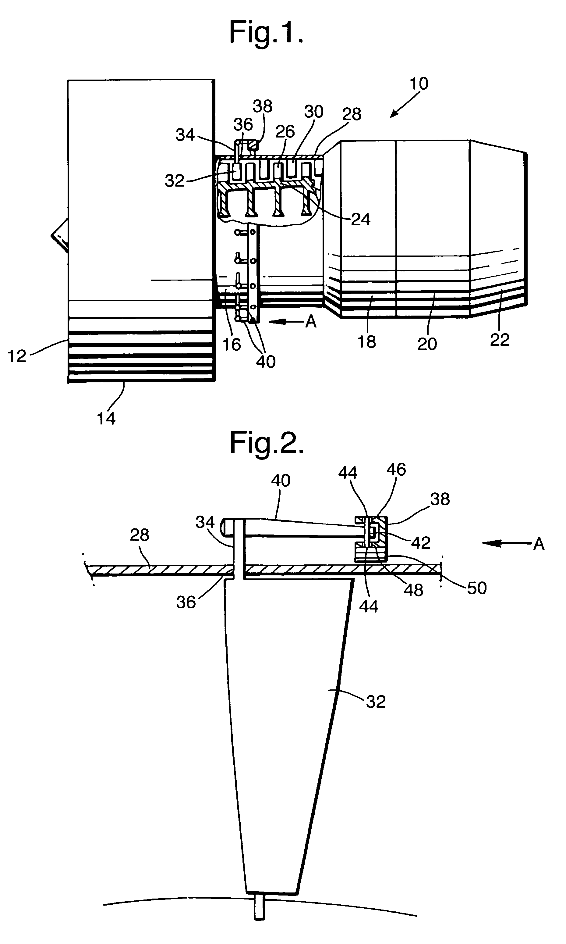
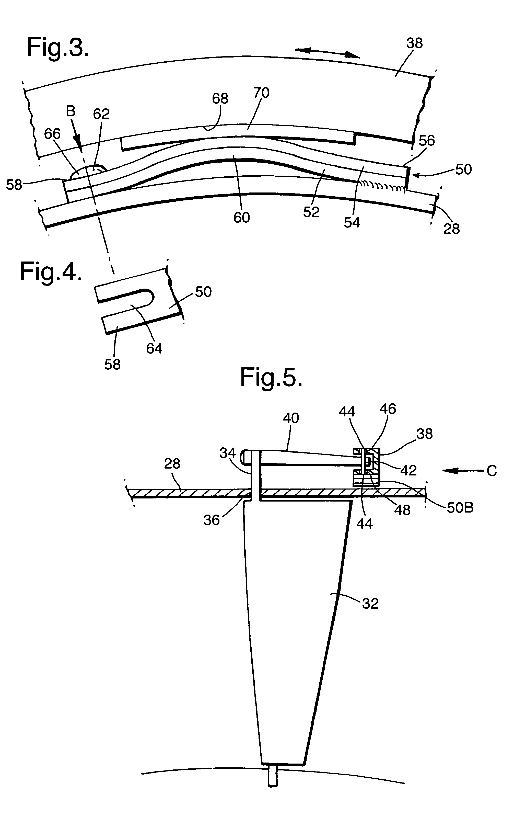
[0037]A turbofan gas turbine engine 10 is shown in FIG. 1, and comprises in axial flow series a fan section 14 which has an intake 12 at its upstream end, a compressor section 16, a combustion section 18, a turbine section 20 and an exhaust 22. The turbofan gas turbine engine 10 operates quite conventionally in that air is taken in through the intake 12, the air is compressed by the fan section 14 and compressor section 16 and is supplied to the combustion section 18. Fuel is injected into, and burnt in, the combustion section 18 to produce hot gases, which flow through and drive the turbine section 20 before flowing through the exhaust 22 to atmosphere. The turbines in the turbine section 20 in turn drive the fan section 14 and compressor section 16 via shafts (not shown).

[0038]The compressor section 16 comprises a rotor 24, which has a plurality of axially spaced stages of rotor blades 26. The rotor blades 26 in each stage are circumferentially spaced and extend radially outwardly...


PUM


Abstract

An axial flow compressor (16) comprises a plurality of variable stator vanes (32) circumferentially spaced apart and extending radially. Each variable stator vane (32) is rotatably mounted on a compressor casing (28). A control ring (38) surrounds the compressor casing (28). Each variable stator vane (32) is connected to the control ring (38) by a respective one of a plurality of operating levers (40) and the control ring (38) is spaced from the compressor casing (28) by a clearance. A plurality of bimetallic strips (50) are arranged circumferentially and are positioned radially between the control ring (38) and the compressor casing (28) and the bimetallic strips (50) control the clearance between the control ring (38) and the compressor casing (28) whereby any error of the variable stator vane (32) angular position is reduced. Each bimetallic strip (50) extends radially outwardly from the compressor casing (28) towards the control ring (38). Each bimetallic strip (50) comprises a first metal strip (52) bonded to a second metal strip (54) and the first metal strip (52) has a different coefficient of thermal expansion than the second metal strip (54).

Description

FIELD OF THE INVENTION[0001]The present invention relates to a variable stator vane arrangement for a compressor, and in particular to a variable stator vane arrangement for a gas turbine engine.BACKGROUND OF THE INVENTION[0002]The compressors of gas turbine engines are generally provided with variable stator vanes, especially compressors which have relatively high pressure ratios, to ensure that the compressor will operate efficiently over its full speed range. The variable stator vanes are used to correct the angle of incidence of the air onto a stage of rotor blades to angles which they can tolerate without a break down of flow, stall or surge at relatively low compressor pressure speeds.[0003]A variable stator vanes angular position is controlled by an operating lever, which is connected to a control ring positioned generally coaxially with the compressor casing. The control ring is usually moved, or rotated, by a ram so as to adjust the positions of the variable stator vanes.[0...

Claims


Application Information

Patent Timeline
Patent Type & Authority Patents(United States)
IPC IPC(8): F01D9/02F01D17/16F04D29/56
CPCF01D17/162F04D29/563F05D2220/36F05D2260/30F05D2230/642F05D2250/61F05D2300/50212
Inventor EVANS, DALE E
Owner ROLLS ROYCE PLC
Why Eureka
Try Eureka