
Adhesive applicator with rotary valve
- Summary
- Abstract
- Description
- Claims
- Application Information
AI Technical Summary
Benefits of technology
Problems solved by technology
Method used
Image

Examples
Example
[0031]Corresponding reference characters indicate corresponding parts throughout the drawings.
DETAILED DESCRIPTION OF THE DRAWINGS
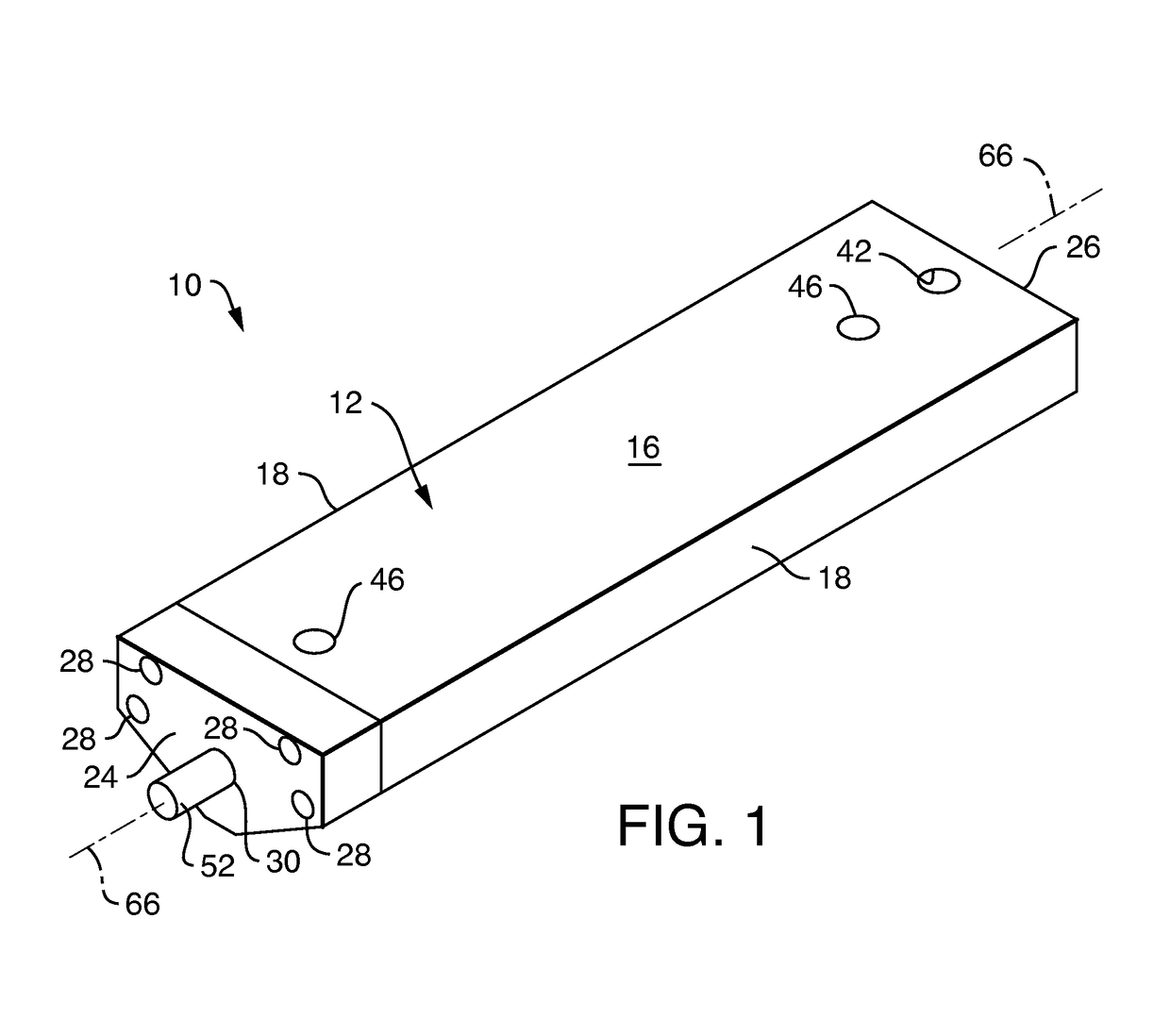
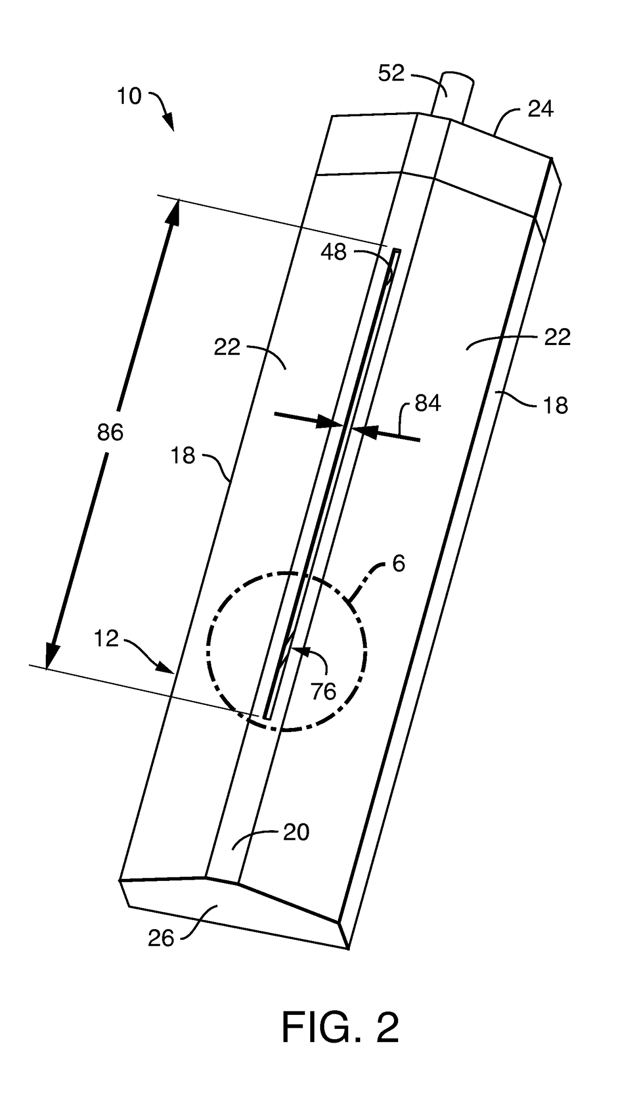
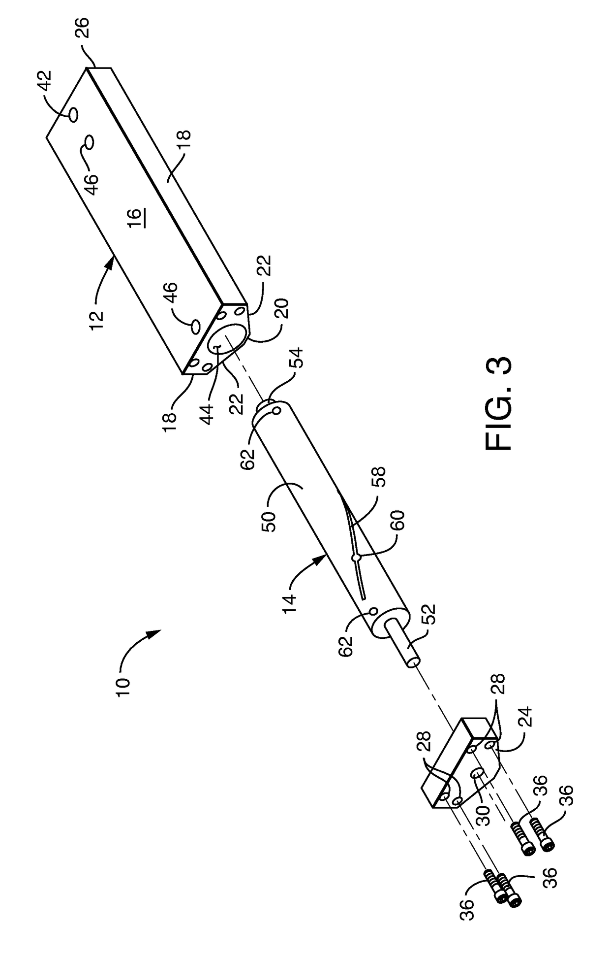
[0032]FIGS. 1-3 illustrate one embodiment of an adhesive applicator, which is indicated generally at 10. FIG. 1 is a topside perspective view of an exemplary embodiment of an applicator of the present invention. FIG. 2 is a bottom side perspective view of the applicator of FIG. 1. FIG. 3 is an exploded perspective view of the applicator of FIG. 1. The applicator comprises a housing, indicated generally at 12, and a rotor, indicated generally at 14 (FIG. 3). The rotor 14 is rotatably mounted within the housing 12. In the illustrated embodiment, the housing 12 has a generally planar top wall 16 and two side walls 18 extending downward from the top wall (FIG. 1). As seen in FIG. 2, the housing 12 also has a generally planar bottom wall 20 and two sloping walls 22 extending between respective ones of the side walls 18 and the bottom wall 20. In the illustrate...
PUM
 Abstract
Description
Claims
Application Information