Heating Apparatus

Inactive Publication Date: 2010-04-15
RICHMOND SIMON NICHOLAS
View PDF27 Cites 8 Cited by
  • Summary
  • Abstract
  • Description
  • Claims
  • Application Information

AI Technical Summary

Benefits of technology

[0014]The power cord includes a control switch assembly for varying the power to the at least one flexible electrical heating element from the vehicle power supply.
[0015]The control switch assembly is operative in one embodiment to change the amoun

Problems solved by technology

However, guiding the power cable to the power socket when such cable exits at the front of the car seat has the problem of a risk of entanglement with the legs of a driver of the vehicle using the seat heater and thus potentially interfering with the driver's ability to appropriately use the brake pedal, accelerator pedal or clutch pedal and thus creating a potentially dangerous driving hazard or causing the driver to trip on the power cable upon exiting the vehicle and thus having a potentially dangerous fall.
These specific locations are to avoid the risk of tangling the heated seat cover power cable with the legs of the driver and thus restricting use of the floor pedals by the driver thus creating a potentially dangerous driving hazard.
This raises their inventory holding levels which is undesirable.
A further problem arises with international retailers.
As some vehicles have the driver side on the right side as in Hong Kong and some vehicles have the driver side on the left side as in China, right across the drivable border from Hong Kong, it becomes difficult for a retailer to offer individual models as a “driver-side model” and a “passenger side-model” in this region as there is confusion between the models.
A further problem exists with 2nd row passenger seats.
These seats are found both on the passenger side and driver side so marketing 2 models as a “driver-side model” and a passenger-side model” would result in consumer confusion for use with such second row seats.
However, this approach is problematic for the merchandising approaches of some retailers who are unwilling to offer this bundled left and right seat option due to the significantly higher consumer retail cost involved than selling a single seat cover.

Method used


Image

  • Heating Apparatus
  • Heating Apparatus
  • Heating Apparatus

Examples


Embodiment Construction

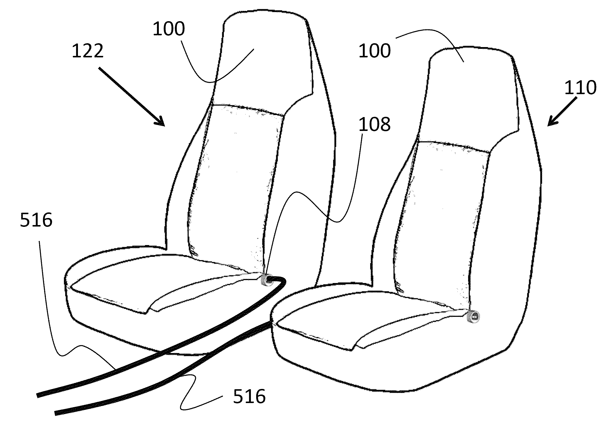
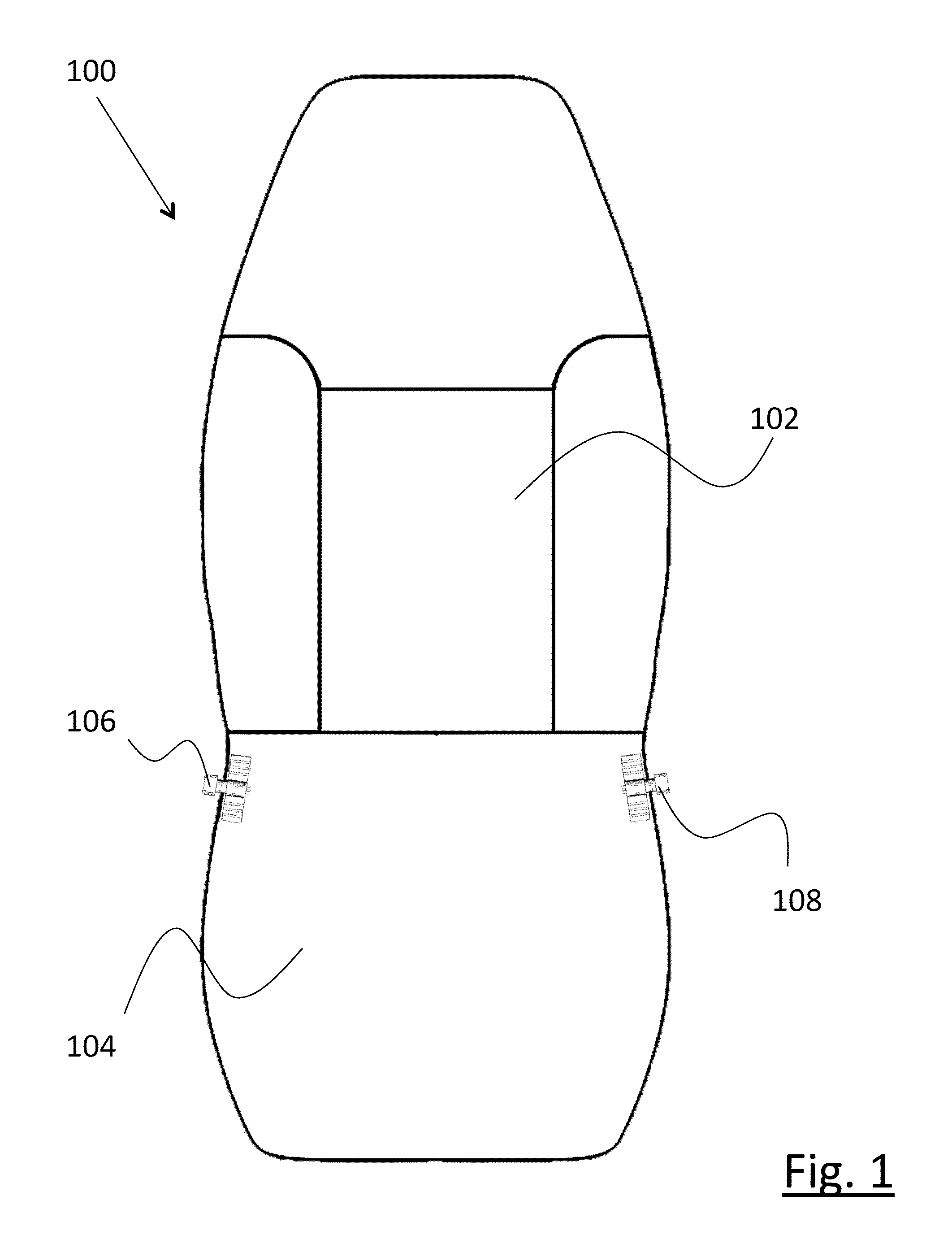
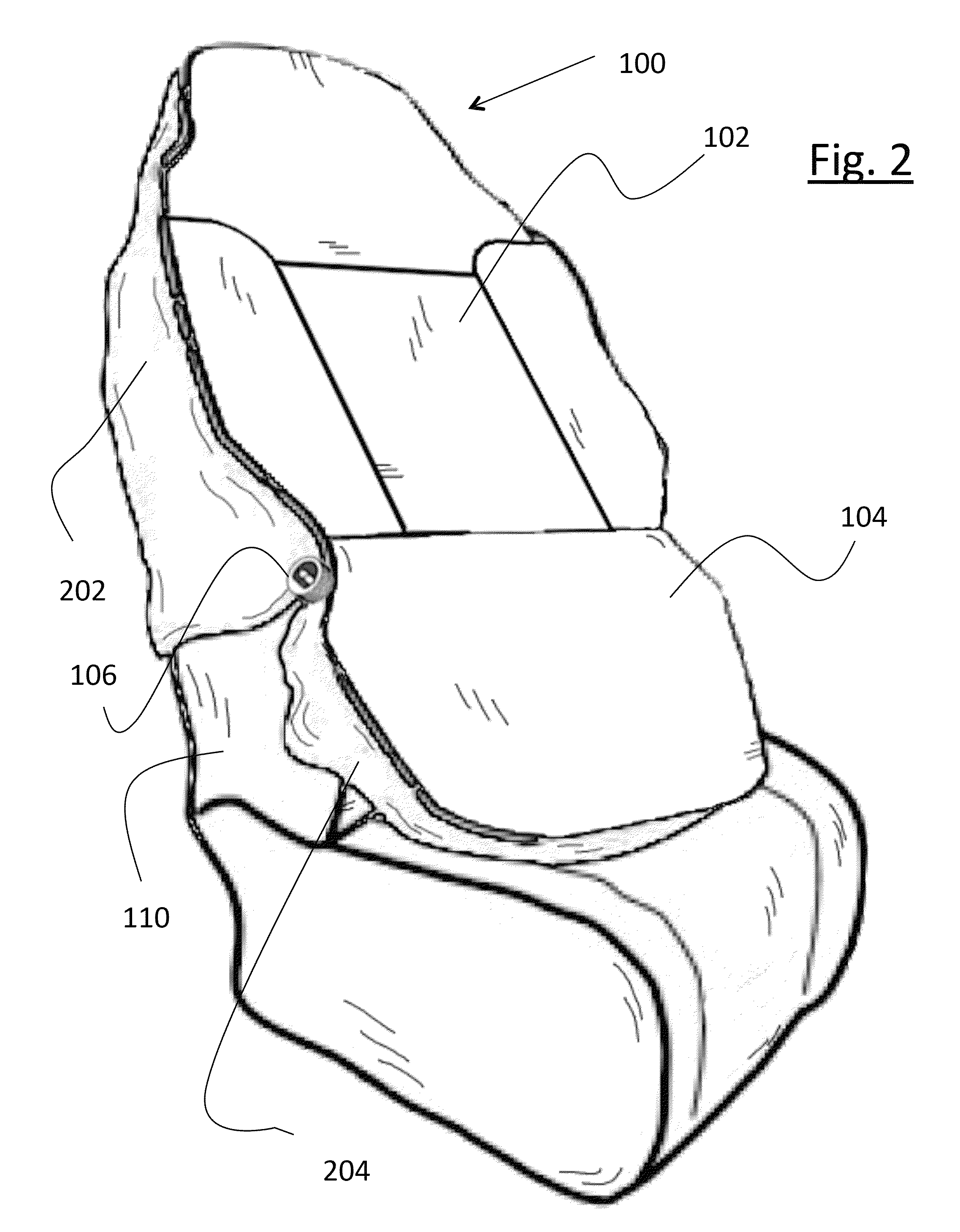
[0037]With reference to the drawings for purposes of illustration, FIG. 1 shows a heated car seat cover assembly having a removable vehicle seat cover portion 100 that comprises a back portion 100 and a seat portion 104. Advantageously, affixed to the main removable vehicle seat cover portion 100 adjacent to the intersection of the back portion 100 and the seat portion 104 is a bilaterally accessible power coupler located along at least one side of the heated car seat cover assembly which in the presently preferred embodiment is in the form of two bilaterally positioned connectors each along the sides of the assembly identified as a first left side connector 108 and a second right side connector 106. The term “bilaterally accessible power coupler” should not be limited to this preferred embodiment, but is intended to include connectors positioned on both sides of the assembly or a single connector (not shown) separated assembly by a cable that is releasably mounted on the assembly a...


PUM


Abstract

The present invention is embodied in a heating apparatus having a removable vehicle seat cover having a back portion and a seat portion with at least one electrical heating element affixed to the removable vehicle seat cover. A power cord is included having a vehicle coupler releasably connectable to a vehicle power supply and at least one controller connector for releasable electrical connection to the at least one electrical heating element. A bilaterally accessible power coupler is located along at least one side of the removable vehicle seat cover and is connected in circuit with the at least one heating element. The bilaterally accessible power coupler and the at least one controller connector are formed complementary to create an electrical connection; and, when the removable vehicle seat cover is installed over a vehicle seat, the bilaterally accessible power coupler is located outside regions of the removable vehicle seat cover typically in contact with a torso and legs of an individual seated in the vehicle seat.

Description

CROSS REFERENCE TO RELATED APPLICATION(S)[0001]This application claims the benefit of U.S. Provisional Application Ser. No. 61 / 195,969, filed on Oct. 14, 2008; the contents of which are all hereby incorporated by reference.BACKGROUND OF THE INVENTION[0002]1. Field of the Invention[0003]The present invention relates to a portable heating apparatus and, more particularly, to a heating apparatus for a removable vehicle seat cover of a vehicle.[0004]2. Description of the Related Art[0005]With the advent of after market heating devices for vehicle seats, such devices tend to have a power cable exiting the seat heater at a single front region of the car seat or at a single side of the car seat. Normally, this power cable needs to be connected to a lighter or power socket located relatively centrally on a front console so it is accessible from either driver or passenger sides. However, guiding the power cable to the power socket when such cable exits at the front of the car seat has the pr...

Claims


Application Information

Patent Timeline
IPC IPC(8): B60L1/02H05B1/00
CPCH05B3/34H05B2203/005H05B2203/029H05B2203/016H05B2203/014
Inventor RICHMOND, SIMON NICHOLAS
Owner RICHMOND SIMON NICHOLAS
Why Eureka
Try Eureka