Needle assembly

a technology of needles and assemblies, applied in the field of needle assemblies, can solve the problems of hubs not providing means to prevent users, spinal and epidural needles are somewhat difficult to manipulate by surgeons or anesthesiologists, etc., and achieve the effect of preventing the coring of the needl

Inactive Publication Date: 2018-12-13
SMITHS MEDICAL ASD INC
View PDF0 Cites 0 Cited by
  • Summary
  • Abstract
  • Description
  • Claims
  • Application Information

AI Technical Summary

Benefits of technology

The patent text describes a needle assembly with a partition that provides stability and prevents accidental rolling on a flat surface. The partition also prevents the user's fingers from touching the needle at the closed end. The needle hub has a connector that only fits with a complementary counterpart connector, and a keyway to guide the insertion of a stylet without coring the needle. These features improve the handling and safety of the needle assembly.

Problems solved by technology

Some of the prior art spinal and epidural needles tend to be somewhat difficult to manipulate by a surgeon or anesthesiologist, when inserting the needle into the patient.
However, those needle hubs do not provide means to prevent the user from inadvertently making contact with the needle or guide the insertion of the needle to the patient, or have a connector that prevents mis-connection.

Method used


Image

  • Needle assembly
  • Needle assembly
  • Needle assembly

Examples


Embodiment Construction

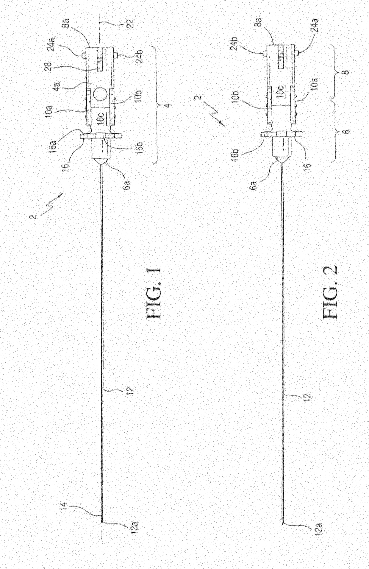
[0022]With reference to the figures, needle assembly 2 of the instant invention is shown to have a needle hub 4 that includes a distal portion 6 and a proximal portion 8. It should be appreciated that although designated as such in FIG. 2, there is no actual line of demarcation between distal portion 6 and proximal portion 8. Distal portion 6 has a closed distal end 6a, whereas proximal portion 8 has an opened proximal end 8a. Needle hub 4 has a main body 4a that is substantially cylindrical along proximal portion 8 and slopes or inclines downwards in a conical fashion towards distal end 6a along distal portion 6.

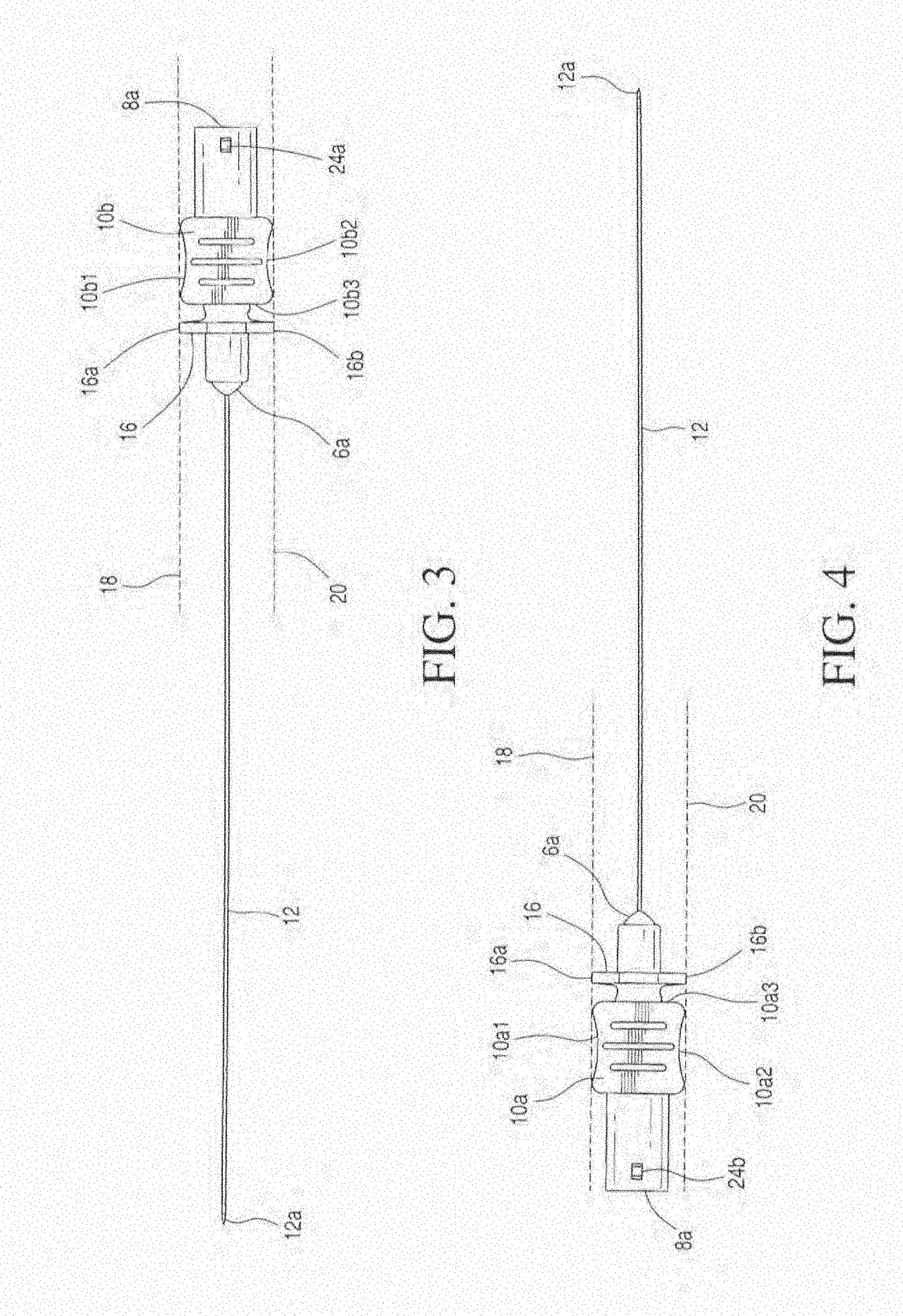
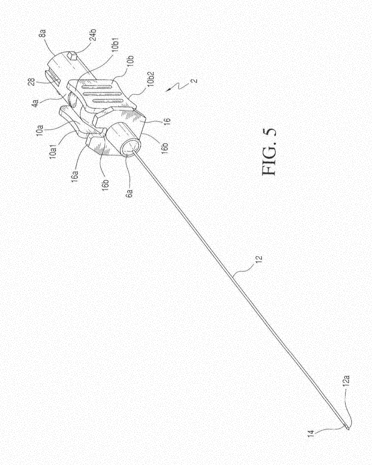
[0023]Two flats or plates 10a and 10b are bonded to body 4a bridging distal portion 6 and proximal portion 8. Plates 10a and 10b each are substantially rectangular in shape, with their respective upper edges 10a1, 10b1 and their respective lower edges 10a2 and 10b2, slightly curved inwardly to form a slight concave configuration. For the instant invention, the respective up...


PUM


Abstract

A needle assembly has a needle hub that has a body to which are formed two plates at opposite sides thereof in a parallel relationship. The plates have respective upper edges and lower edges that lie substantially along respective planes, so that the needle hub may be stably placed onto a surface by means of the respective edges. A partition is formed orthogonally proximate to the front ends of the parallel plates. The partition and the parallel plates together provide upper and lower three point stable supports for the needle hub. A notch at the partition provides a guided line of sight to the tip of the needle for the user. The connector at the proximal portion of the needle hub has a non-conventional configuration that allows it to mate only with a counterpart special connector of a fluid conveying device that has a complementary non-conventional configuration.

Description

CROSS REFERENCES TO RELATED APPLICATIONS[0001]This application is a continuation-in-part application of application Ser. No. 13 / 567,122 filed on Aug. 6, 2012.FIELD OF THE INVENTION[0002]The present invention relates to needle assemblies, and particularly to a needle assembly that has a specially designed hub that enables a user to firmly grasp and manipulate the needle for insertion to a patient. The connector end of the hub has a non-conventional configuration that prevents the needle hub from connecting to conventional counterpart connectors.BACKGROUND OF THE INVENTION[0003]Some of the prior art spinal and epidural needles tend to be somewhat difficult to manipulate by a surgeon or anesthesiologist, when inserting the needle into the patient. The prior art does disclose some needle hubs that have means for the user to grasp. Such prior art includes U.S. Pat. Nos. 6,027,480, D378,405, D421,119 and D469,870. However, those needle hubs do not provide means to prevent the user from in...

Claims


Application Information

Patent Timeline
Patent Type & Authority Applications(United States)
IPC IPC(8): A61M5/32A61B17/34
CPCA61M5/3287A61M2205/6045A61M5/3293A61B17/3401A61M2205/586
Inventor CLARK, GEOFF
Owner SMITHS MEDICAL ASD INC
Why Eureka
Try Eureka