Motor lead connector for ingress protected motor

a lead connector and ingress protection technology, applied in the field of motors, can solve problems such as difficult replacement, if not impossible, of permanent connections

Active Publication Date: 2018-12-13
NIDEC MOTOR CORP
View PDF2 Cites 6 Cited by
  • Summary
  • Abstract
  • Description
  • Claims
  • Application Information

AI Technical Summary

Problems solved by technology

Conventional molded connectors often interfere with cooling along the surface of the motor case, require extensive alignment operations between the connector and the con

Method used


Image

  • Motor lead connector for ingress protected motor
  • Motor lead connector for ingress protected motor
  • Motor lead connector for ingress protected motor

Examples


Embodiment Construction

[0028]The present invention is susceptible of embodiment in many different forms. While the drawings illustrate, and the specification describes, certain preferred embodiments of the invention, it is to be understood that such disclosure is by way of example only. There is no intent to limit the principles of the present invention to the particular disclosed embodiments.

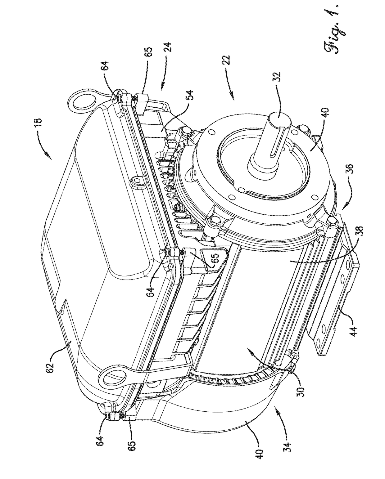
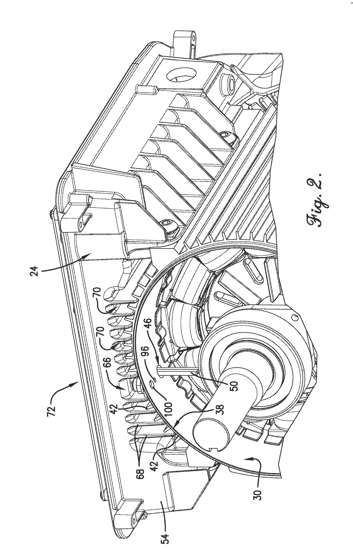
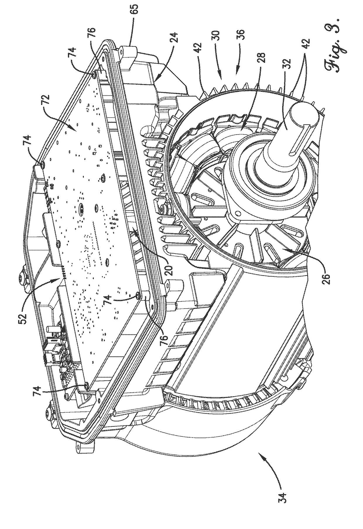
[0029]With initial reference to FIGS. 1-5, a motor assembly 18 includes a lead connector 20 (see FIG. 4) constructed in accordance with an embodiment of the present invention. The lead connector 20 is configured for attachment to an electric motor 22 and for sealing against the electric motor 22 and a controller housing 24. The lead connector 20 provides electrical connection between components in the motor 22 and in the controller housing 24.

[0030]As is generally customary, the motor 22 broadly includes a rotor assembly 26, rotatable about an axis, and a stator assembly 28. The rotor assembly 26 and the stator assem...


PUM


Abstract

An electric motor having a rotor, a stator, a case at least partially enclosing the rotor and the stator, and a lead connector. The lead connector includes a body having a base, a terminal end, and an intermediate portion extending between the base and the terminal end. The lead connector also includes a first sealing interface extending substantially circumferentially about the intermediate portion and a second sealing interface abutting the case.

Description

CROSS-REFERENCE TO RELATED APPLICATION[0001]The present application claims the benefit of and priority from identically-titled U.S. Provisional Patent Application Ser. No. 62 / 518,370, filed Jun. 12, 2017, the entire disclosure of which is hereby incorporated by reference herein.BACKGROUND OF THE INVENTIONField of the Invention[0002]The present invention relates generally to motors. More specifically, the present invention concerns a lead connector for a motor that is particularly configured to enhance the ingress protection of the motor.Discussion of the Prior Art[0003]Those of ordinary skill in the art will appreciate that electric motors typically include a controller that governs parameters of how the motor operates (for example, speed and direction). The motor controller may be programmable, which can allow a motor with a given construction to be programmed to operate in a certain desirable manner, as may be particularly advantageous when the motor is coupled with a driven machi...

Claims


Application Information

Patent Timeline
IPC IPC(8): H02K5/10H01R13/52H01R13/631H01R13/621
CPCH02K5/10H01R13/5219H01R13/5202H01R13/631H01R13/6215H01R12/718H01R2105/00H01R2201/10H02K5/18H02K5/225H02K11/33
Inventor MAJOR, MICHAEL W.BELLEY, RICHARD A.CORCORAN, MARC J.
Owner NIDEC MOTOR CORP
Why Eureka
Try Eureka