High-dynamic-range video tone mapping

a dynamic range and video tone technology, applied in the field of video processing, can solve problems such as poor video quality

Active Publication Date: 2019-01-17
MEDIATEK INC
View PDF0 Cites 16 Cited by
  • Summary
  • Abstract
  • Description
  • Claims
  • Application Information

AI Technical Summary

Benefits of technology

This patent describes methods for processing high dynamic range (HDR) videos by converting them into different colors spaces, adjusting their brightness levels through a gradual process called tonemapping, and creating new frames based on the original ones. These techniques help improve the quality and appearance of HDR videos when displayed on screens with standard dynamic ranges.

Problems solved by technology

High dynamic range (HDR) technology has been developed but current methods used to convert HDR videos to standard dynamic range (SDR) can result in poor video quality due to static tonemapping curves that fail to adapt to changes in frames within the video. There is thus a technical problem requiring an improved video controller and method for performing tone-mapping of HDR video to address this issue.

Method used


Image

  • High-dynamic-range video tone mapping
  • High-dynamic-range video tone mapping
  • High-dynamic-range video tone mapping

Examples


Embodiment Construction

[0016]The following description is of the best-contemplated mode of carrying out the invention. This description is made for the purpose of illustrating the general principles of the invention and should not be taken in a limiting sense. The scope of the invention is best determined by reference to the appended claims.

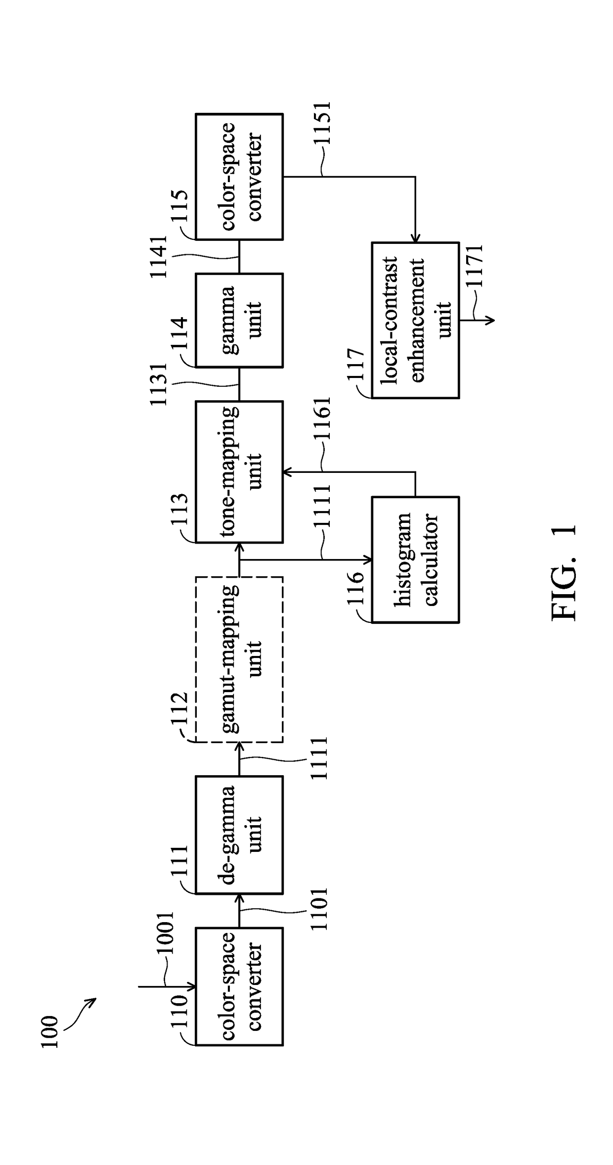
[0017]FIG. 1 is a block diagram of a video controller in accordance with an embodiment of the invention. As shown in FIG. 1, the video controller 100 includes a color-space converter 110, a de-gamma unit 111, a gamut mapping unit 112, a tone-mapping unit 113, a gamma unit 114, a color-space converter 115, a histogram calculator 116, a local-contrast enhancement unit 117, and a histogram calculator 118. The video controller 100 can be electrically connected to a display panel 120 via a multimedia transmission interface such as high-definition multimedia interface (HDMI) version 2.0 A or above, and the display panel 120 may display the output linear RGB video signal from...


PUM


Abstract

A video controller and method for performing tone-mapping of high-dynamic-range (HDR) video are provided. The video controller includes: a color-space converter, arranged to receive an input high-dynamic-range (HDR) video signal and perform a color space conversion on the input HDR video signal to obtain a first video signal having a first gamma curve; a de-gamma unit, arranged to apply a second gamma curve on the first video signal to compensate the first gamma curve to obtain a second video signal; a first histogram calculator, arranged to calculate a first histogram of a current frame of the second video signal; and a tone-mapping unit, arranged to apply a tone-mapping curve on the current frame of the second video signal according to a histogram of a previous frame of the second video signal to generate an output video signal.

Description


Claims


Application Information

Patent Timeline
Owner MEDIATEK INC
Why Eureka
Try Eureka