Recoil-damping device

a recoil damping and gun technology, applied in the direction of weapons, butts, weapons, etc., can solve the problems of only achieving the effect of recoil damping for the user, jamming of the trigger element in the guide sleeve, etc., to avoid or reduce injuries or at least unpleasantness for the shooter, and dampen the recoil

Active Publication Date: 2019-02-14
SCHOENBORN DAMIAN
View PDF2 Cites 0 Cited by
  • Summary
  • Abstract
  • Description
  • Claims
  • Application Information

AI Technical Summary

Benefits of technology

[0003]Devices for damping a recoil acting on a shooter as a result of the firing of a gun are known from the prior art. These devices are configured on the one hand to damp the recoil as effectively as possible in order to avoid or reduce injuries or at least unpleasantness for the shooter and on the other hand to maintain as far as possible a precise target acquisition by the shooter before delivery of a shot and during delivery of a shot sequence. A rigid configuration of the recoil-damping device before delivery of the shot is favorable for the target acquisition.
[0004]US 2002 / 0053156 A1 discloses a gun with a recoil-damping device and a locking device. The locking device allows the effect, in particular a compression, of the recoil-damping device only after an impulse weight accelerated by a shot releases a lock. In this way, an unintentional compression of the recoil-damping device before actuation of the trigger is prevented during aiming at a target. The recoil damping device, which comprises a damping spring and the locking device are arranged between a rear and a front butt part which are displaceable with respect to one another. The locking device comprises ball catches in which balls engage in recesses in a rod connected to the front butt part and a sleeve connected to the rear butt part in order to be able to lock the compression or release from engagement in order to enable compression. A disadvantage of this construction is that the impulse weight in order to release the lock must overcome a frictional resistance produced as a result of its sliding movement so that it is necessary to overcome a relatively high frictional resistance for a reliable triggering of the damping effect.

Problems solved by technology

A disadvantage of this construction is that the impulse weight in order to release the lock must overcome a frictional resistance produced as a result of its sliding movement so that it is necessary to overcome a relatively high frictional resistance for a reliable triggering of the damping effect.
As a result of this type of latching connection, however, a comparatively large shock impulse is disadvantageously required to release the locking connection, with the result that the aim of a recoil damping for the user is only achieved to a certain extent.
Instead of such pivotable components, intermeshing components subject to wear or triggering elements sliding along large-area, possibly contaminated contact surfaces are known from the prior art.
In addition, manufacturing tolerances which could result in a jamming of the triggering element in the guide sleeve if no possibility of pivoting is provided can be compensated.

Method used


Image

  • Recoil-damping device
  • Recoil-damping device
  • Recoil-damping device

Examples


Embodiment Construction

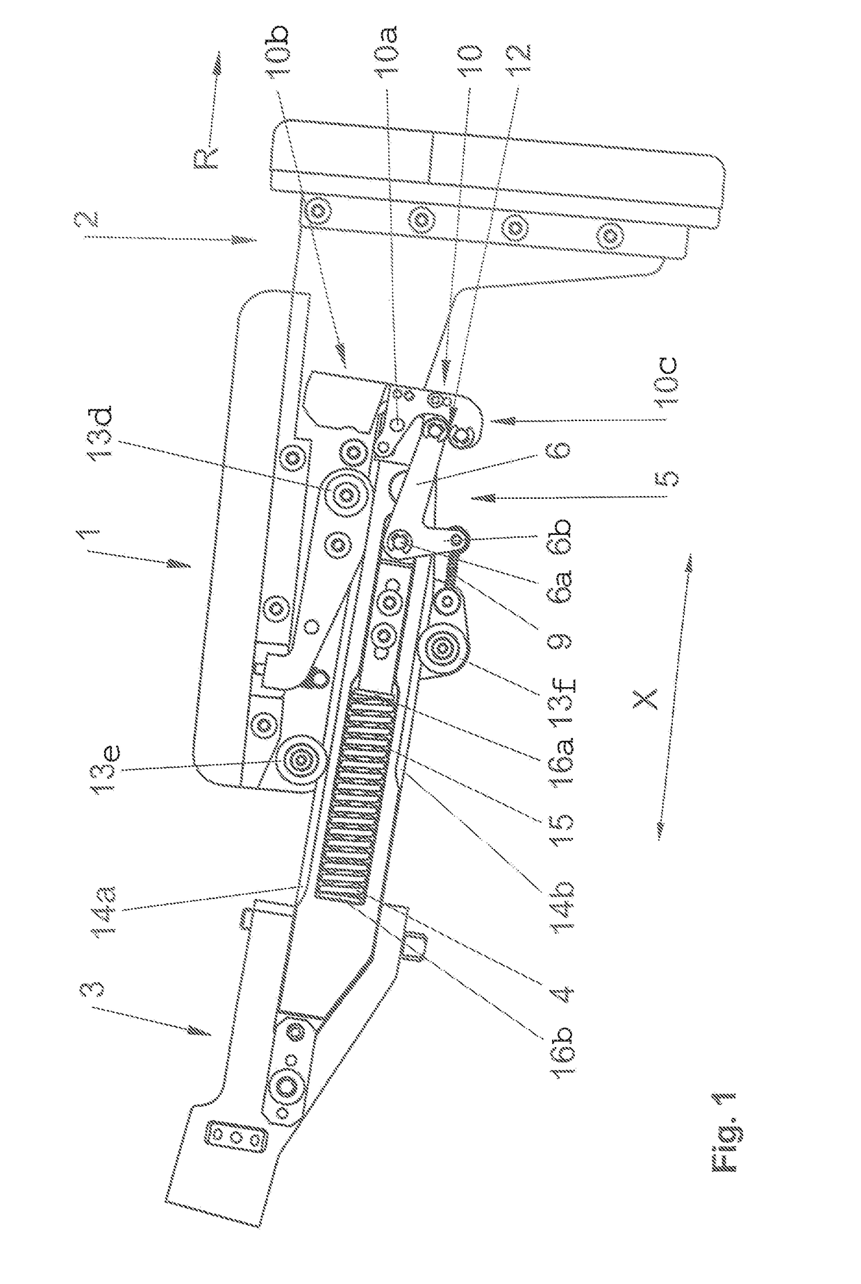
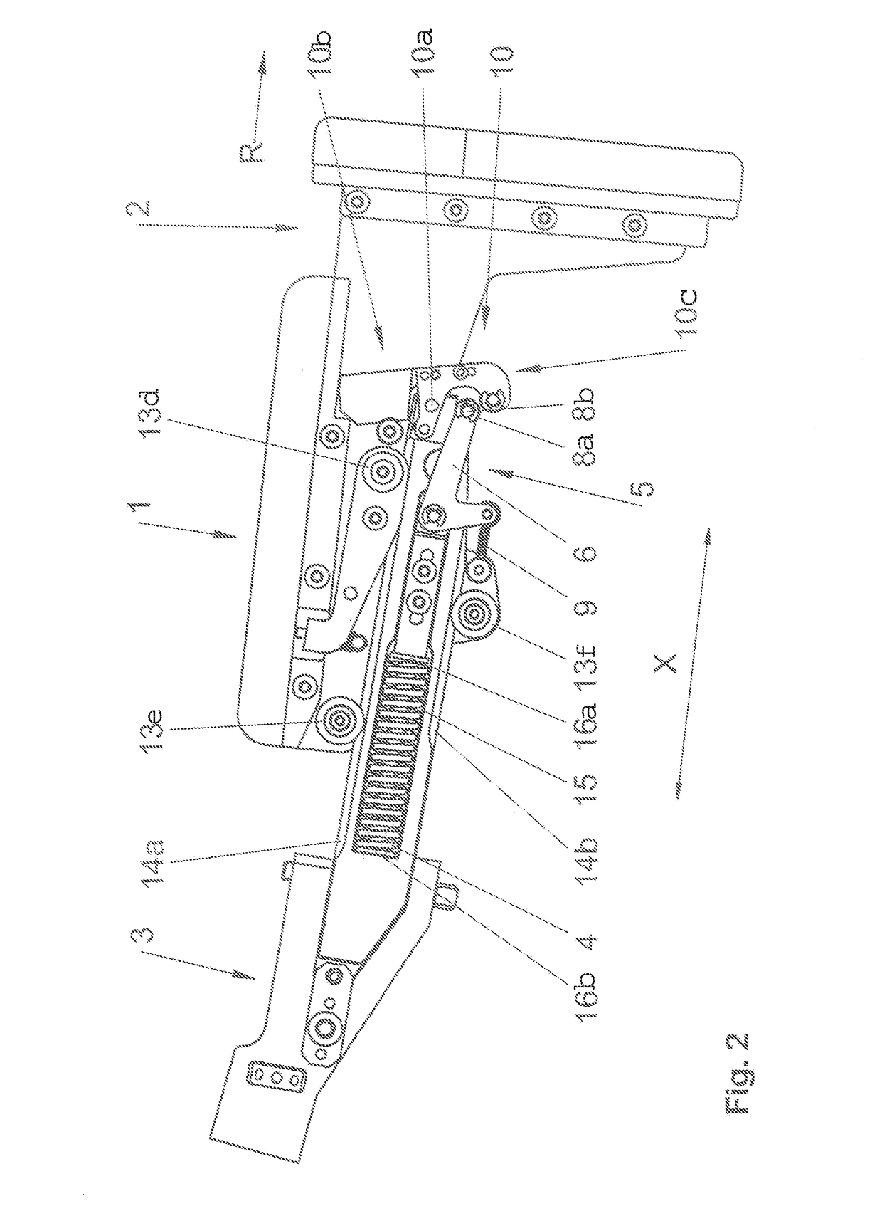
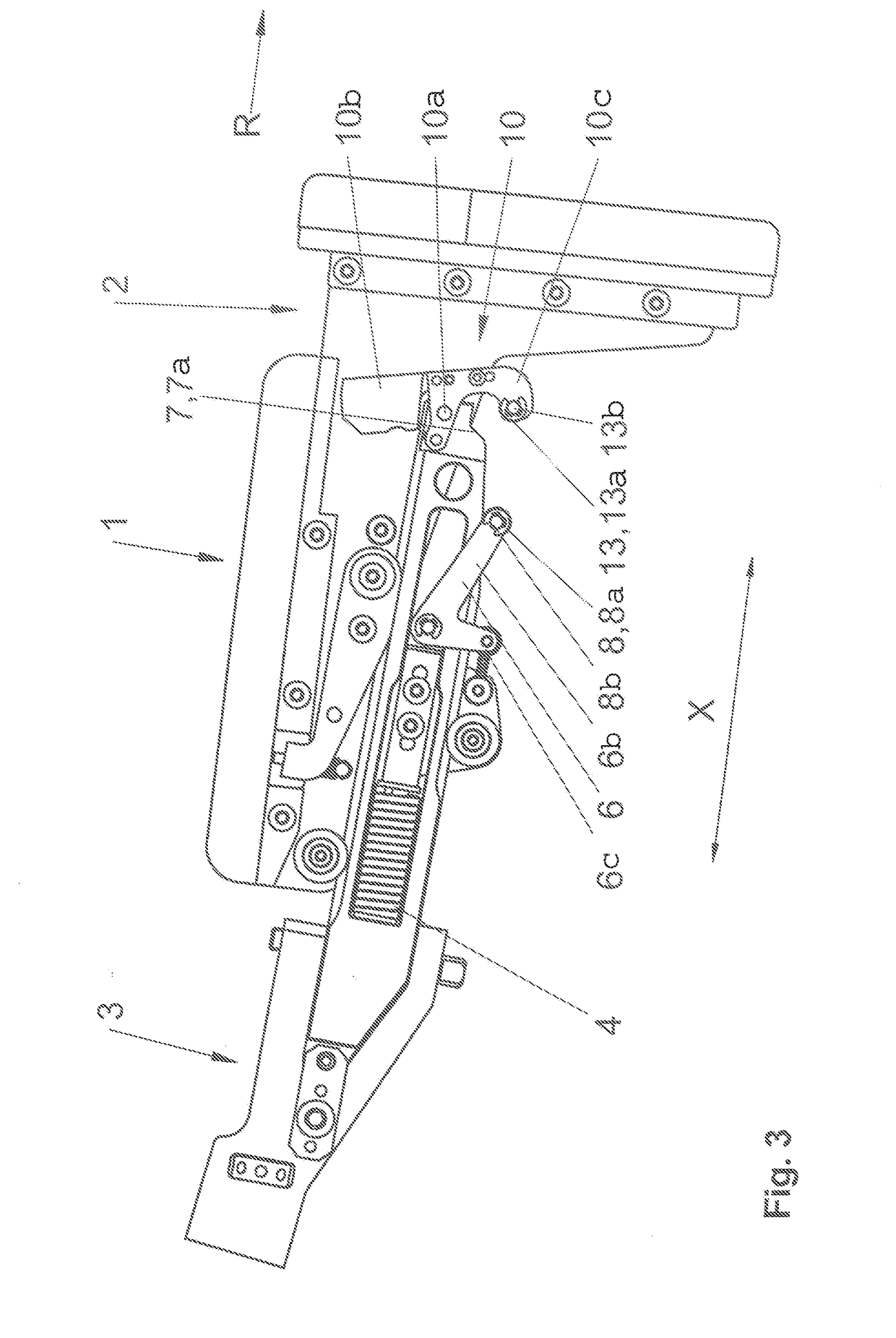
[0038]FIG. 1 shows a recoil-damping device 1 for a gun, for fastening on or in a buttstock of the gun, the buttstock serving as the rest of the gun on the shoulder of a shooter and is not shown. The recoil-damping device 1 comprises a rear part 2 and a front part 3 which are movable against one another against the force of a damping element 4, in the present example a helical spring. The rear part 2 which is more distant to the barrel of the gun than the front part 3, and the front part 3 can be installed in a buttstock of the gun which buttstock consists of parts which can be displaced with respect to / against one another. Alternatively, if e.g. the gun has no buttstock consisting of parts which can be displaced with respect to one another, it can be retrofitted with the recoil-damping device 1 by mounting the front part 3 on the rear-side end of the buttstock. A locking device 5 is provided between the rear part 2 and the front part 3 which locking device 5, in a locking position s...


PUM


Abstract

A recoil-damping device for a gun, in particular for fastening onto or in a buttstock of the gun, having a rear part and a front part which are movable towards one another against the force of at least one damping element. A locking device acting between the rear part and the front part is provided, which in a locking position blocks a relative movement between the rear and front parts and in a release position allows a relative movement between the rear and the front parts. A triggering element which can be activated by means of a shock pulse is further provided, which in a holding position holds the locking device in the locking position and in an active position releases the locking device into the release position. The triggering element and / or at least a part of the locking device is pivotable as a result of the shock pulse.

Description

CROSS REFERENCE TO RELATED APPLICATIONS[0001]The present application is a continuation of U.S. patent application Ser. No. 15 / 517,935, entitled “RECOIL-DAMPING DEVICE,” filed on Apr. 7, 2017. U.S. patent application Ser. No. 15 / 517,935 is a U.S. National Phase of International Application No. PCT / AT2016 / 060027, entitled “RECOIL-DAMPING DEVICE,” filed on Aug. 10, 2016. International Application No. PCT / AT2016 / 060027 claims priority to Austrian Application No. A 50784 / 2015 filed on Sep. 14, 2015. The entire contents of the above-identified applications are hereby incorporated by reference in their entirety for all purposes.TECHNICAL FIELD[0002]The invention relates to a recoil-damping device for a gun, in particular for fastening onto or in a buttstock of the gun, optionally a handgun, having a rear part and a front part which are movable towards one another against the force of at least one damping element, wherein a locking device acting between rear part and front part is provided,...

Claims


Application Information

Patent Timeline
Patent Type & Authority Applications(United States)
IPC IPC(8): F41C23/06
CPCF41C23/06
Inventor KRONSTEINER, MARTINSCHOENBORN, DAMIAN
Owner SCHOENBORN DAMIAN
Why Eureka
Try Eureka