Patient-specific mandible graft cage

Active Publication Date: 2019-03-14
DEPUY SYNTHES PROD INC
View PDF0 Cites 7 Cited by
  • Summary
  • Abstract
  • Description
  • Claims
  • Application Information

AI Technical Summary

Problems solved by technology

However, without a container for the bone graft material, the graft material may fall away from a target site before it has been incorporated by the body into the healing bone.

Method used


Image

  • Patient-specific mandible graft cage
  • Patient-specific mandible graft cage

Examples


Embodiment Construction

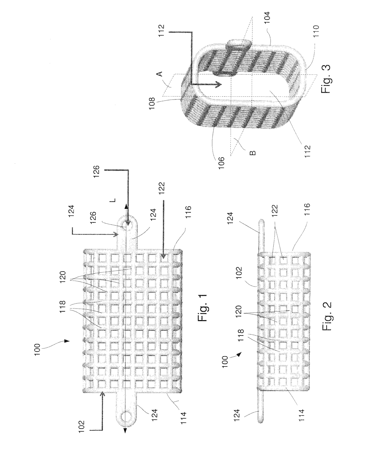
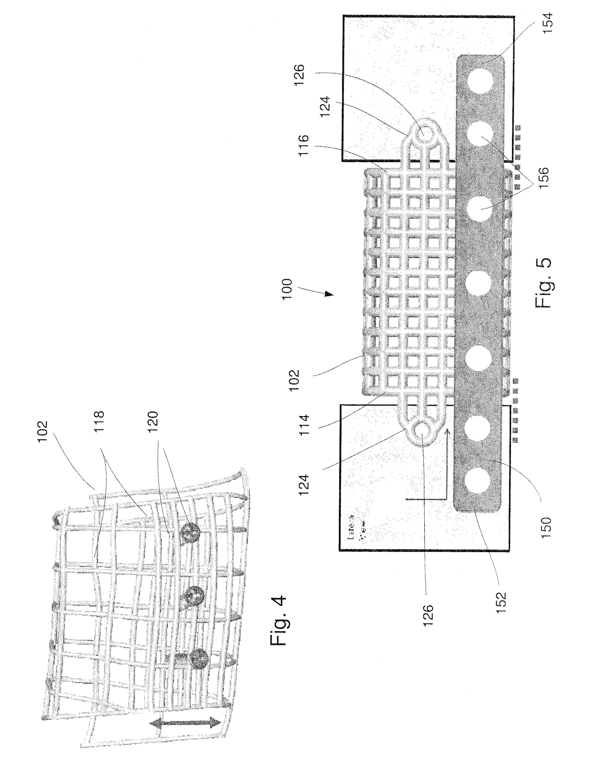
[0009]The present invention may be understood with reference to the following description and the appended drawings, wherein like elements are referred to with the same reference numerals. The present invention relates to the treatment of bone and, in particular, relates to treatments using bone grafts and bone graft substitutes. Exemplary embodiments of the present invention describe a patient-specific graft containment cage configured to be positioned in a gap or space in a target bone (e.g., the mandible) so that graft material may be packed therein to encourage and guide the growth of new bone into the gap / space. In one exemplary embodiment, the cage is positioned between two separated portions of bone to generate new bone joining the separated portions of bone. It will be understood by those of skill in the art, however, that the graft containment cage may be inserted or positioned within any gap or space in the target bone including, for example, at an end of the bone, so that...


PUM


Abstract

A method for treating a mandible including forming an initial digital 3D model of a mesh graft containment device based on dimensions of a target space of a mandible to be filled via the graft containment device, the 3D model of the graft containment device defined via a buccal surface, a lingual surface, a superior surface and an inferior surface, individually adjusting one of the buccal surface and the lingual surface relative to a first midplane, which extends through a longitudinal axis of the graft containment device between the buccal and lingual surfaces, to add or remove bulk along a desired portion of the 3D model of the graft containment device to form an adjusted 3D model, and forming a final graft containment device for placement in the target space of the mandible based on the adjusted 3D model.

Description

BACKGROUND[0001]Mandible defects are often treated with bone grafts and / or implants such as, bone plates, to assist with healing. The bone graft material may be placed in the target area using any of a variety of methods. However, without a container for the bone graft material, the graft material may fall away from a target site before it has been incorporated by the body into the healing bone.SUMMARY[0002]The present embodiments are directed to a method for treating a mandible, comprising forming an initial digital 3D model of a mesh graft containment device based on dimensions of a target space of a mandible to be filled via the graft containment device, the 3D model of the graft containment device defined via a buccal surface, a lingual surface, a superior surface and an inferior surface, individually adjusting one of the buccal surface and the lingual surface relative to a first midplane, which extends through a longitudinal axis of the graft containment device between the bucc...

Claims


Application Information

Patent Timeline
Patent Type & Authority Applications(United States)
IPC IPC(8): A61F2/28
CPCA61F2/2803A61F2/2846A61F2002/285A61F2002/30945A61F2002/30952A61F2/30942A61F2/30771A61F2002/3092A61F2/2875A61F2002/2835A61F2002/30576A61F2002/3096A61F2002/30943
Inventor DANIEL, STEFFANFURRER, ANDRE
Owner DEPUY SYNTHES PROD INC
Why Eureka
Try Eureka