Orthodontic indirect bonding tray including stabilization features

a technology of stabilization feature and orthodontic appliances, which is applied in the field of indirect bonding tray including stabilization feature, can solve the problems of appliance unintentionally dislodging from its intended location, difficulty in accessing the surface of malposed teeth, and difficulty in seeing the precise position of the bracket relative to the tooth surfa

Active Publication Date: 2015-12-17
CARRILLO GONZALEZ ROBERTO J +1
View PDF4 Cites 16 Cited by
  • Summary
  • Abstract
  • Description
  • Claims
  • Application Information

AI Technical Summary

Problems solved by technology

For example, access to surfaces of malposed teeth may be difficult.
In some instances, and particularly in connection with posterior teeth, the practitioner may have difficulty seeing the precise position of the bracket relative to the tooth surface.
Additionally, the appliance may be unintentionally dislodged from its intended location during the time that the excess adhesive is being removed adjacent the base of the appliance.
For example, improper fit of the transfer tray over the patient's teeth is a common problem.
An improperly fitted transfer tray may result in appliances being bonded to locations on the patient's teeth that are imprecise and do not correspond to the previous location of the same appliance on the stone model.
As a result, malpositioned teeth may move to unintended positions during the treatment program.
Although the transfer tray is fabricated to match the surfaces of the patient's teeth, as is often the case, the transfer tray may be somewhat unstable, loose, or inaccurate.
Such instability can result from several factors.
For example, inaccuracies may arise during the steps leading up to the fabrication of the transfer tray.
Inaccuracies may arise during fabrication of the impression of the patient's teeth, or during the fabrication of the stone model based upon each impression.
Inaccuracies may also arise during bonding of the appliances to the stone model at desired locations.
Additionally, inaccuracies may arise due to the fact that the transfer tray is customarily fabricated of a material that is insufficiently rigid.
Due to any one or a combination of the foregoing factors, a certain amount of instability, “wiggle”, or “play” often arises when the transfer tray is placed over matching surfaces of the patient's teeth during the indirect bonding process.
The potential for such instability increases, especially when the transfer tray is arranged for placement over only a small number of teeth, e.g., two or three teeth.
Other than its surfaces that match a patient's teeth, currently available transfer trays (made for one or multiple teeth) do not provide the practitioner with such a feature or mechanism.

Method used


Image

  • Orthodontic indirect bonding tray including stabilization features
  • Orthodontic indirect bonding tray including stabilization features
  • Orthodontic indirect bonding tray including stabilization features

Examples


Embodiment Construction

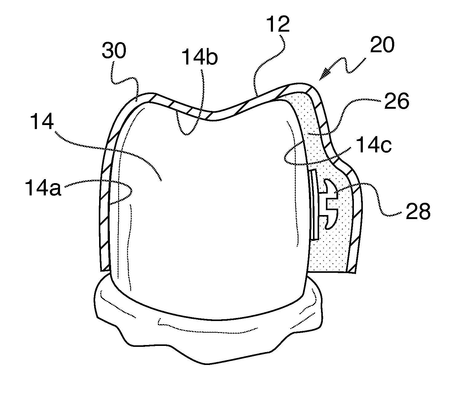
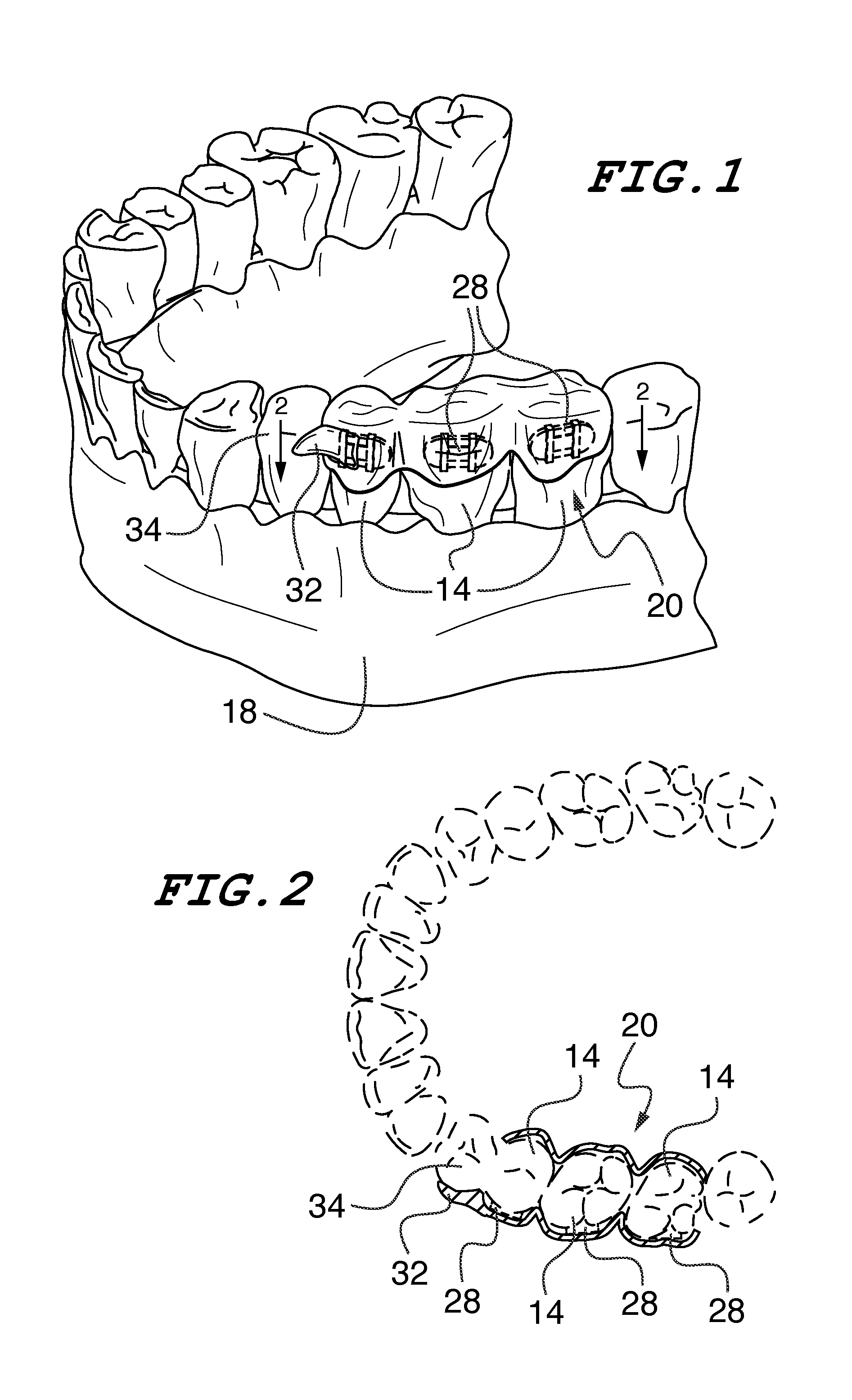
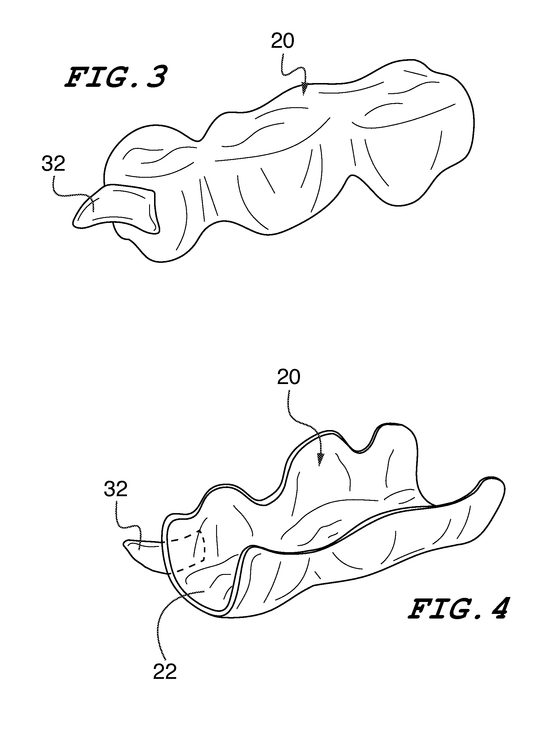
[0022]Referring now in greater detail to the drawings in which like numerals represent like components throughout the several views, there is shown in FIGS. 1-5 an embodiment of the orthodontic indirect bonding tray including stabilization features of the present invention which is broadly designated by the numeral 20. As best shown in FIGS. 1 and 2, the bonding tray 20 is shown positioned over several teeth 14 of the upper jaw 18, or maxilla, of an orthodontic patient, the teeth 14 requiring corrective orthodontic alignment. FIG. 1 illustrates the upper dental arch rotated one-hundred eighty degrees to illustrate the occlusal surfaces of the teeth located therein. Although the figures illustrate the indirect bonding tray of the present invention positioned over teeth of the upper jaw, it should be understood that it is within the scope of the present invention that the bonding tray 20 could be positioned over teeth of the lower jaw.

[0023]The tray 20 includes a channel 22 (FIG. 4) c...


PUM


Abstract

A tray for use in bonding orthodontic appliances to selected teeth of a patient is disclosed. The tray includes an outer shell having wall sections extending over facial, lingual, and occlusal surfaces of the selected teeth to form a channel including tooth cavities having a configuration matching and arranged for receiving the selected teeth. A matrix is bonded to the inner surface of the outer shell and is contoured to complement the facial or lingual surface of the teeth. A stabilization member extends from the outer shell and includes an inside surface contoured to complement at least a portion of the facial surface of a tooth located adjacent the selected teeth. Orthodontic appliances are detachably connected to the matrix, wherein each appliance includes a base for bonding the appliance to a tooth.

Description

FIELD OF THE INVENTION[0001]This invention relates to method and apparatus for bonding orthodontic appliances such as brackets to a patient's teeth. The present invention specifically relates to an indirect bonding tray including stabilization features.BACKGROUND OF THE INVENTION[0002]Orthodontic treatment involves movement of malpositioned teeth to desired locations in the oral cavity. Orthodontic treatment can improve the patient's facial appearance, especially in instances where the teeth are noticeably crooked or where the jaws are out of alignment with each other. Orthodontic treatment can also enhance the function of the teeth by providing better occlusion during mastication.[0003]One common type of orthodontic treatment involves the use of tiny, slotted appliances known as brackets. The brackets are fixed to the patient's teeth and an arch wire is placed in the slot of each bracket. The arch wire forms a track to guide movement of teeth to desired locations.[0004]The ends of ...

Claims


Application Information

Patent Timeline
Patent Type & Authority Applications(United States)
IPC IPC(8): A61C7/14
CPCA61C7/146
Inventor CARRILLO GONZALEZ, ROBERTO J.FUENTEVILLA, ROBERTO CARRILLO
Owner CARRILLO GONZALEZ ROBERTO J
Why Eureka
Try Eureka